FT260 HID-CLASS USB TO UART/I2C BRIDGE IC
Version 1.1
Document No.: FT_001272 Clearance No.: FTDI#484
5.3.1 UART Pin Definition
The UART function in the FT260 can be configured as UART-only or I2C plus UART mode by DCNF0 and
DCNF1 pins. The mode selection is as shown in the Table 5.2.
The pins of the FT260 will be mapped accordingly. The UART pins are
Receive Data (RXD)
– DIO3 (pin-10 @ WQFN28)
– DIO4 (pin-11 @ WQFN28)
– DIO0 (pin-7 @ WQFN28)
serial data input.
Transmit Data (TXD)
serial data output.
Transmit Active signal (TX_ACTIVE)
active high when data transmission is in progress. Asserted one clock cycle before start bit and
de-asserted with final stop bit.
Request To Send Signal (RTSN)
active low handshaking bit. When low it indicates that the UART can start receiving Rx Data.
Clear To Send Signal (CTSN) – DIO2 (pin-9 @ WQFN28)
– DIO1 (pin-8 @ WQFN28)
active low handshaking bit. When this bit is ‘1’, the UART should stop sending TX Data.
Data Terminal Ready (DTRN) – DIO9 (pin-16 @ WQFN28)
active low and when ‘0’, indicates that the UART can be connected and receive RX Data.
Data Set Ready (DSRN) – DIO13 (pin-28 @ WQFN28)
active low indicating an active connection. When this bit is ‘1’, the UART should not send TX Data.
Data Carrier Detect (DCD) – DIO10 (pin-17 @ WQFN28)
asserted when a connection has been established with external device.
Ring Indicator (RI)
– DIO11 (pin-18 @ WQFN28)
asserted when requested to wake up.
5.3.2 UART Bus Protocol
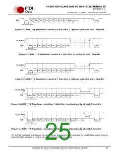
Data transferring uses NRZ (Non-Return to Zero) data format consisting of 1 start bit, 7 or 8 data bits, an
optional parity bit, and one or two stop bits.
.
.
Data Bits - 7 data bits or 8 data bits.
Parity Bit - No parity.
- Odd parity. This means that the parity bit is set to either ‘1’ or ‘0’ so that an odd
number of 1’s are sent.
- Even parity. This means that the parity bit is set to either ‘1’ or ‘0’ so that an even
number of 1’s are sent.
- High parity. This simply means that the parity bit is always High.
- Low parity. This simply means that the parity bit is always Low.
.
Stop Bits - one bit or two bits.
When transmitting the data bits, the least significant bit is transmitted first. UART transmitting and
receive waveforms are illustrated in the below figures.
Copyright © Future Technology Devices International Limited
24

 FTDI [ FUTURE TECHNOLOGY DEVICES INTERNATIONAL LTD. ]