FT260 HID-CLASS USB TO UART/I2C BRIDGE IC
Version 1.1
Document No.: FT_001272 Clearance No.: FTDI#484
5.2.3 I2C Slave Address
The FT260 is configured as a USB to I²C master bridge and is able to issue any value of 7-bits slave
address. Users can issue I2C commands towards an I2C slave device to read or write data via the
applications defined in USB host side. For details, refer to the FT260 Application Notes.
When the FT260 is powered up, the I2C master controller will start to scan the external I2C device. The
scanning address range is from 50h to 57h for the types of EEPROM. For further details refer to section
9.2.
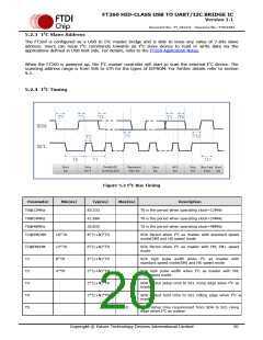
5.2.4 I2C Timing
Figure 5.2 I2C Bus Timing
Parameter
T0@12MHz
T0@24MHz
T0@48MHz
T1@SM/HM
Min(ns)
Typ(ns)
83.333
Max(ns)
Description
T0 is the period when operating clock=12MHz
T0 is the period when operating clock=24MHz
T0 is the period when operating clock=48MHz
41.666
20.833
16*T0
8*(1+N)*T0
SCK Period when I2C as master with standard speed
mode(SM) and HS speed mode
T1@FM/HM
12*T0
8*T0
4*T0
6*(1+N)*T0
4*(1+N)*T0
2*(1+N)*T0
2*(1+N)*T0
2*(1+N)*T0
SCK Period when I2C as master with FM, FM+ speed
mode
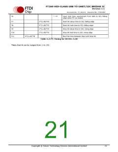
T2
T2
T3
T4
T5
SCK high pulse width when I2C as master with
standard speed mode(SM) and HS speed mode
SCK high pulse width when I2C as master with FM,
FM+ speed mode
SDA output setup time to SCL rising edge when I2C as
master
SDA output hold time to SCL falling edge when I2C as
master
>=0
input setup time requirement from SDA to SCL rising
edge when I2C as master
Copyright © Future Technology Devices International Limited
20

 FTDI [ FUTURE TECHNOLOGY DEVICES INTERNATIONAL LTD. ]