FT260 HID-CLASS USB TO UART/I2C BRIDGE IC
Version 1.1
Document No.: FT_001272 Clearance No.: FTDI#484
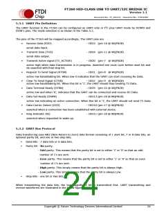
5.3.3 UART Flow Control
The UART interface needs to implement proper flow control to prevent data from being lost by the
external device. This will be done using either hardware or software flow control. The FT260 UART
supports the modes listed below.
OFF, and switch UART pins to GPIO
RTS_CTS mode (hardware flow control)
DTR_DSR mode (hardware flow control)
XON_XOFF (software flow control)
No flow control mode
RTS/CTS Hardware Flow Control
When RTS / CTS flow control is used, the CTS input indicate to the FT260 that the data communications
equipment (DCE) is ready to receive data. If it is active (low), then the FT260 is free to transmit data on
the TX data line, otherwise it has to hold the data until CTS goes low. The RTS output is used to indicate
that The FT260 is capable of receiving data (active low). Thus, it should be set inactive by the FT260
when both the UART receive register and receive holding register are full.
DTR/DSR Hardware Flow Control
These signals are provided to give information about the status of each UART. When this mode is enabled
and the DTS input is high, the FT260 UART should not send any data on the TX line. DTR will be enabled
on reset and a register bit will allow the IO Bus to alter the state at any time.
Software Flow Control
When software flow control is enabled the XON character and XOFF character are used to stop and start
the flow of data. The XON character tells the downstream device to start sending data. The XOFF
character tells the downstream device to stop sending data. Typical defaults for XON is `11’ and for XOFF
is `13’.
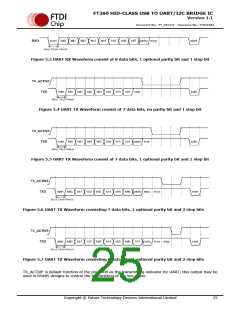
5.3.4 UART Timing
Figure 5.8 UART Timing
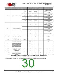
Parameter
T0@48MHz
T1
Min(ns)
-2500ppm
4*T0
Typ(ns)
Max(ns)
+2500ppm
40000*T0
Description
T0 is the period when operating clock=48MHz
Baud clock period of txd
20.833
Table 5.4 UART Timing
Copyright © Future Technology Devices International Limited
26

 FTDI [ FUTURE TECHNOLOGY DEVICES INTERNATIONAL LTD. ]