Freescale Semiconductor, Inc.
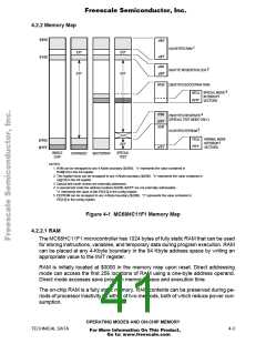
4.2.2 Memory Map
$0000
x000
1
1024 BYTES RAM
EXT
EXT
EXT
x3FF
y000
$1000
2
96-BYTE REGISTER BLOCK
EXT
y05F
BF00 256 BYTES BOOTSTRAP ROM
3
SPECIAL MODE
INTERRUPT
VECTORS
BFC0
BFFF
zD00
4
256 BYTES RESERVED
(SPECIAL TEST MODE ONLY)
zDFF
zE00
5
512 BYTES EEPROM
NORMAL MODE
INTERRUPT
VECTORS
FFC0
FFFF
$FE00
$FFFF
EXT
zFFF
SINGLE
CHIP
SPECIAL
TEST
EXPANDED
BOOTSTRAP
NOTES:
1. RAM can be remapped to any 4-Kbyte boundary ($x000). "x" represents the value contained in
RAM[3:0] in the init register.
2. The register block can be remapped to any 4-Kbyte boundary ($y000). "y" represents the value contained in
reg[3:0] in the init register.
3. Special test mode vectors are externally addressed.
4. In special test mode the address locations $zD00–$zDFF are not externally addressable.
"z" represents the value of bits EE[3:0] in the config register.
5. EEPROM can be remapped to any 4-Kbyte boundary ($z000). "z" represents the value contained in
EE[3:0] in the config register.
Figure 4-1 MC68HC11F1 Memory Map
4.2.2.1 RAM
The MC68HC11F1 microcontroller has 1024 bytes of fully static RAM that can be used
for storing instructions, variables, and temporary data during program execution. RAM
can be placed at any 4-Kbyte boundary in the 64 Kbyte address space by writing an
appropriate value to the INIT register.
RAM is initially located at $0000 in the memory map upon reset. Direct addressing
mode can access the first 256 locations of RAM using a one-byte address operand.
Direct mode accesses save program memory space and execution time.
The on-chip RAM is a fully static memory. RAM contents can be preserved during pe-
riods of processor inactivity by either of two methods, both of which reduce power con-
sumption.
OPERATING MODES AND ON-CHIP MEMORY
TECHNICAL DATA
4-3
For More Information On This Product,
Go to: www.freescale.com

 FREESCALE [ Freescale ]