Central Processor Unit (CPU)
CPU Registers
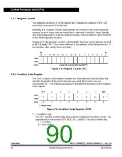
H — Half-Carry Flag
The CPU sets the half-carry flag when a carry occurs between accumulator bits
3 and 4 during an add-without-carry (ADD) or add-with-carry (ADC) operation.
The half-carry flag is required for binary-coded decimal (BCD) arithmetic
operations. The DAA instruction uses the states of the H and C flags to
determine the appropriate correction factor.
1 = Carry between bits 3 and 4
0 = No carry between bits 3 and 4
I — Interrupt Mask
When the interrupt mask is set, all maskable CPU interrupts are disabled. CPU
interrupts are enabled when the interrupt mask is cleared. When a CPU
interrupt occurs, the interrupt mask is set
automatically after the CPU registers are saved on the stack, but before the
interrupt vector is fetched.
1 = Interrupts disabled
0 = Interrupts enabled
NOTE:
To maintain M6805 Family compatibility, the upper byte of the index register (H) is
not stacked automatically. If the interrupt service routine modifies H, then the user
must stack and unstack H using the PSHH and PULH instructions.
After the I bit is cleared, the highest-priority interrupt request is serviced first.
A return-from-interrupt (RTI) instruction pulls the CPU registers from the stack
and restores the interrupt mask from the stack. After any reset, the interrupt
mask is set and can be cleared only by the clear interrupt mask software
instruction (CLI).
N — Negative flag
The CPU sets the negative flag when an arithmetic operation, logic operation,
or data manipulation produces a negative result, setting bit 7 of the result.
1 = Negative result
0 = Non-negative result
Z — Zero flag
The CPU sets the zero flag when an arithmetic operation, logic operation, or
data manipulation produces a result of $00.
1 = Zero result
0 = Non-zero result
C — Carry/Borrow Flag
The CPU sets the carry/borrow flag when an addition operation produces a
carry out of bit 7 of the accumulator or when a subtraction operation requires a
borrow. Some instructions — such as bit test and branch, shift, and rotate —
also clear or set the carry/borrow flag.
1 = Carry out of bit 7
0 = No carry out of bit 7
MC68HC908MR32 • MC68HC908MR16 — Rev. 6.0
MOTOROLA Central Processor Unit (CPU)
Data Sheet
91

 FREESCALE [ Freescale ]