Freescale Semiconductor, Inc.
Serial Communications Interface (SCI)
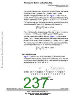
For an 8-bit character, data sampling of the stop bit takes the receiver
9 bit times × 16 RT cycles + 10 RT cycles = 154 RT cycles.
With the misaligned character shown in Figure 17-8, the receiver
counts 154 RT cycles at the point when the count of the transmitting
device is 10 bit times × 16 RT cycles = 160 RT cycles.
The maximum percent difference between the receiver count and the
transmitter count of a fast 8-bit character with no errors is
154 – 160
× 100 = 3.90%
-------------------------
154
For a 9-bit character, data sampling of the stop bit takes the receiver
10 bit times × 16 RT cycles + 10 RT cycles = 170 RT cycles.
With the misaligned character shown in Figure 17-8, the receiver
counts 170 RT cycles at the point when the count of the transmitting
device is 11 bit times × 16 RT cycles = 176 RT cycles.
The maximum percent difference between the receiver count and the
transmitter count of a fast 9-bit character with no errors is
170 – 176
× 100 = 3.53%
-------------------------
170
17.5.3.6 Receiver Wakeup
So that the MCU can ignore transmissions intended only for other
receivers in multiple-receiver systems, the receiver can be put into a
standby state. Setting the receiver wakeup bit, RWU, in SCC2 puts the
receiver into a standby state during which receiver interrupts are
disabled.
Depending on the state of the WAKE bit in SCC1, either of two
conditions on the RxD pin can bring the receiver out of the standby state:
• Address mark — An address mark is a logic 1 in the most
significant bit position of a received character. When the WAKE bit
is set, an address mark wakes the receiver from the standby state
by clearing the RWU bit. The address mark also sets the SCI
receiver full bit, SCRF. Software can then compare the character
containing the address mark to the user-defined address of the
Technical Data
MC68HC908AS60 — Rev. 1.0
Serial Communications Interface (SCI)
For More Information On This Product,
Go to: www.freescale.com

 FREESCALE [ Freescale ]