Parallel Host Interface (HDI08)
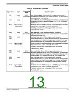
Table 2-9 Host Interface (continued)
State During
Signal Name
Type
Signal Description
Reset
HA2
Input
GPIO
Host Address Input 2—When the HDI08 is programmed to interface a
Disconnected non-multiplexed host bus and the HI function is selected, this signal is line 2
of the host address (HA2) input bus.
HA9
Input
Host Address 9—When HDI08 is programmed to interface a multiplexed host
bus and the HI function is selected, this signal is line 9 of the host address
(HA9) input bus.
PB10
Input, Output, or
Disconnected
Port B 10—When the HDI08 is configured as GPIO, this signal is individually
programmed as input, output, or internally disconnected.
The default state after reset for this signal is GPIO disconnected.
This input is 3.3V tolerant.
HRW
Input
Input
GPIO
Host Read/Write—When HDI08 is programmed to interface a
Disconnected single-data-strobe host bus and the HI function is selected, this signal is the
Host Read/Write (HRW) input.
HRD/
HRD
Host Read Data—When HDI08 is programmed to interface a
double-data-strobe host bus and the HI function is selected, this signal is the
host read data strobe (HRD) Schmitt-trigger input. The polarity of the data
strobe is programmable, but is configured as active-low (HRD) after reset.
PB11
Input, Output, or
Disconnected
Port B 11—When the HDI08 is configured as GPIO, this signal is individually
programmed as input, output, or internally disconnected.
The default state after reset for this signal is GPIO disconnected.
This input is 3.3V tolerant.
HDS/
HDS
Input
Input
GPIO
Host Data Strobe—When HDI08 is programmed to interface a
Disconnected single-data-strobe host bus and the HI function is selected, this signal is the
host data strobe (HDS) Schmitt-trigger input. The polarity of the data strobe
is programmable, but is configured as active-low (HDS) following reset.
HWR/
HWR
Host Write Data—When HDI08 is programmed to interface a
double-data-strobe host bus and the HI function is selected, this signal is the
host write data strobe (HWR) Schmitt-trigger input. The polarity of the data
strobe is programmable, but is configured as active-low (HWR) following
reset.
PB12
Input, Output, or
Disconnected
Port B 12—When the HDI08 is configured as GPIO, this signal is individually
programmed as input, output, or internally disconnected.
The default state after reset for this signal is GPIO disconnected.
This input is 3.3V tolerant.
DSP56367 Technical Data, Rev. 2.1
Freescale Semiconductor
2-9

 FREESCALE [ Freescale ]