Freescale Semiconductor, Inc.
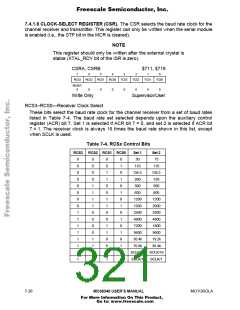
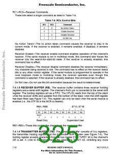
7.4.1.6 CLOCK-SELECT REGISTER (CSR). The CSR selects the baud rate clock for the
channel receiver and transmitter. This register can only be written when the serial module
is enabled (i.e., the STP bit in the MCR is cleared).
NOTE
This register should only be written after the external crystal is
stable (XTAL_RDY bit of the ISR is zero).
CSRA, CSRB
$711, $719
7
6
5
4
3
2
1
0
RCS3
RCS2
RCS1
RCS0
TCS3
TCS2
TCS1
TCS0
RESET:
0
0
0
0
0
0
0
0
Write Only
Supervisor/User
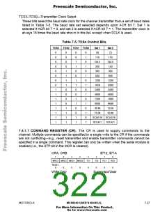
RCS3–RCS0—Receiver Clock Select
These bits select the baud rate clock for the channel receiver from a set of baud rates
listed in Table 7-4. The baud rate set selected depends upon the auxiliary control
register (ACR) bit 7. Set 1 is selected if ACR bit 7 = 0, and set 2 is selected if ACR bit
7 = 1. The receiver clock is always 16 times the baud rate shown in this list, except
when SCLK is used.
Table 7-4. RCSx Control Bits
RCS3
RCS2 RCS1 RCS0
Set 1
50
Set 2
75
0
0
0
0
0
0
0
0
1
1
1
1
1
1
1
1
0
0
0
0
1
1
1
1
0
0
0
0
1
1
1
1
0
0
1
1
0
0
1
1
0
0
1
1
0
0
1
1
0
1
0
1
0
1
0
1
0
1
0
1
0
1
0
1
110
110
134.5
200
134.5
150
300
300
600
600
1200
1050
2400
4800
7200
9600
38.4k
76.8k
1200
2000
2400
4800
1800
9600
19.2k
38.4k
SCLK/16 SCLK/16
SCLK/1 SCLK/1
7- 26
MC68340 USER’S MANUAL
MOTOROLA
For More Information On This Product,
Go to: www.freescale.com

 FREESCALE [ Freescale ]