Freescale Semiconductor, Inc.
6.4.2 Dual-Address Mode
The dual-address DMA bus cycle transfers data between a device or memory and the
DMA internal holding register (DHR). In this mode, any operand transfer takes place in
two DMA bus cycles, one where a device is addressed and one where memory is
addressed. The data transferred during a dual-address operation is either read from the
data bus into the DHR or written from the DHR to the data bus.
Each DMA channel can each be programmed to operate in the dual-address transfer
mode. In this mode, the operand is read from the source address specified in the SAR and
placed in the DHR. The operand read may take up to four bus cycles to complete because
of differences in operand sizes of the source and destination. The operand is then written
to the address specified in the DAR. This transfer may also be up to four bus cycles long.
In this manner, various combinations of peripheral, memory, and operand sizes may be
used. See 6.7 Register Description for more information.
The dual-address transfers can be started by either the internal request mode or by an
external device using the DREQ≈ input signal. When the external device uses DREQ≈, the
channel can be programmed to operate in either burst transfer mode or cycle steal mode.
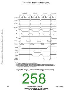
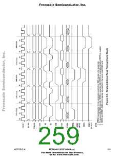
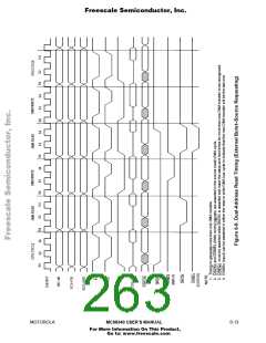
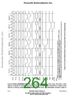
6.4.2.1 DUAL-ADDRESS READ. During the dual-address read cycle, the DMA reads data
from a device or memory into the internal DHR. The device or memory is selected by the
address specified in the SAR, the source function codes in the FCR, and the source size
in the CCR. Data is read from the memory or peripheral and placed in the DHR when the
bus cycle is terminated. When the complete operand has been read, the SAR is
incremented by 0, 1, 2, or 4, according to the size and increment information specified by
the SSIZE and SAPI bits of the CCR. The DMA control signals (DACK≈ and DONE≈) are
asserted in the source (read) cycle when the source device makes a request. See Figures
6-9 and 6-10 for timing diagrams of dual-address read for external burst and cycle steal
modes.
6- 12
MC68340 USER’S MANUAL
MOTOROLA
For More Information On This Product,
Go to: www.freescale.com

 FREESCALE [ Freescale ]