GENERAL RELEASE SPECIFICATION
August 27, 1998
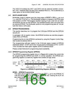
A.3 PERSONALITY EPROM (PEPROM)
The 64-bit PEPROM is left blank for user programming.
A.4 MASK OPTION REGISTER
The EPROM programmable Mask Option Register is used for setting EPROM
security and enabling the external pin oscillator.
BIT 7
BIT 6
BIT 5
-
BIT 4
-
BIT 3
-
BIT 2
-
BIT 1
-
BIT 0
-
MOR
R
EPMSEC
OSCS
$002F
W
reset:
erased:
U
0
U
0
U
-
U
-
U
-
U
-
U
-
U
-
U = UNAFFECTED BY RESET
Figure A-2. MC68HC705SB7 Mask Option Register (MOR)
EPMSEC — EPROM Security Bit
1 = Access to the EPROM array in non-user mode is denied.
0 = Access to the EPROM array in non-user mode is enabled.
This write-only bit controls the non-user mode access to the EPROM array on the
MCU. When programmed to “1”, any accesses of the EPROM locations will return
undefined results.
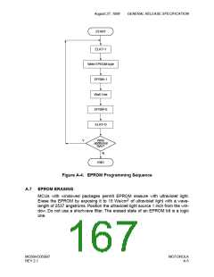
EPMSEC Programming
The state of the EPMSEC security bit should be programmed using a programmer
board (available from Motorola). In order to program the EPMSEC bit the desired
state must be written to the MOR address and then the MPGM bit in the EPROG
register must be used. The following sequence will program the EPMSEC bit:
1. Write the desired data to the EPMSEC bit in MOR.
2. Apply the programming voltage to the IRQ/V pin.
PP
3. Set the MPGM bit in the EPROG.
4. Wait for the programming time (t
).
MPGM
5. Clear the MPGM bit in the EPROG.
6. Remove the programming voltage from the IRQ/V pin.
PP
Once the EPMSEC bit has been programmed to a “1”, access to the contents of
the EPROM in the non-user mode will be denied. It is therefore recommended that
the User EPROM in the part first be programmed and fully verified before setting
the EPMSEC bit.
OSCS — Oscillator Select Bit
1 = External pin oscillator (EPO) enabled.
0 = External pin oscillator (EPO) disabled.
MOTOROLA
A-2
MC68HC05SB7
REV 2.1

 FREESCALE [ Freescale ]