as a typical circuit board trace capacitance the parallel load capacitance presented to the crystal is 9pF as
determined by the following equation:
CL1 * CL2
CL1 + CL2
12 * 12
12 + 12
CL =
+ Cs =
+ 3 = 6 + 3 = 9pF
This is the value load capacitance that should be used when selecting a crystal and determining the actual
frequency of operation of the crystal oscillator circuit.
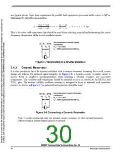
Recommended External Crystal
Parameters:
EXTAL XTAL
Rz
fc
Rz = 1 to 3 MΩ
fc = 8MHz (optimized for 8MHz)
Figure 3-7 Connecting to a Crystal Oscillator
3.4.2
Ceramic Resonator
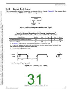
It is also possible to drive the internal oscillator with a ceramic resonator, assuming the overall system
design can tolerate the reduced signal integrity. In Figure 3-8, a typical ceramic resonator circuit is
shown. Refer to supplier’s recommendations when selecting a ceramic resonator and associated
components. The resonator and components should be mounted as close as possible to the EXTAL and
XTAL pins. The internal 56F80x oscillator circuitry is designed to have no external load capacitors
present. As shown in Figure 3-7 no external load capacitors should be used.
Recommended Ceramic Resonator
EXTAL XTAL
Parameters:
Rz = 1 to 3 MΩ
Rz
fc = 8MHz (optimized for 8MHz)
fc
Figure 3-8 Connecting a Ceramic Resonator
Note: Freescale recommends only two terminal ceramic resonators vs. three terminal resonators
(which contain an internal bypass capacitor to ground).
56F807 Technical Data Technical Data, Rev. 16
30
Freescale Semiconductor

 FREESCALE [ Freescale ]