Functional Description
5.3.1
Normal Interrupt Handling
Once the INTC has determined that an interrupt is to be serviced and which interrupt has the highest
priority, an interrupt vector address is generated. Normal interrupt handling concatenates the Vector Base
Address (VBA) and the vector number to determine the vector address, generating an offset into the vector
table for each interrupt.
5.3.2
Interrupt Nesting
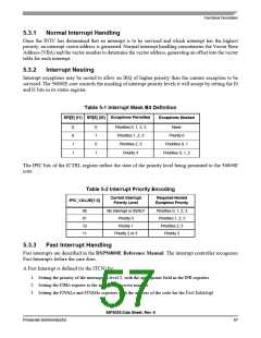
Interrupt exceptions may be nested to allow an IRQ of higher priority than the current exception to be
serviced. The 56800E core controls the masking of interrupt priority levels it will accept by setting the I0
and I1 bits in its status register.
Table 5-1 Interrupt Mask Bit Definition
Exceptions Permitted
SR[9] (I1) SR[8] (I0)
Exceptions Masked
0
0
1
1
0
1
0
1
Priorities 0, 1, 2, 3
Priorities 1, 2, 3
Priorities 2, 3
Priority 3
None
Priority 0
Priorities 0, 1
Priorities 0, 1, 2
The IPIC bits of the ICTRL register reflect the state of the priority level being presented to the 56800E
core.
Table 5-2 Interrupt Priority Encoding
Current Interrupt
Priority Level
Required Nested
Exception Priority
IPIC_VALUE[1:0]
00
01
10
11
No interrupt or SWILP
Priority 0
Priorities 0, 1, 2, 3
Priorities 1, 2, 3
Priorities 2, 3
Priority 3
Priority 1
Priority 2 or 3
5.3.3
Fast Interrupt Handling
Fast interrupts are described in the DSP56800E Reference Manual. The interrupt controller recognizes
Fast Interrupts before the core does.
A Fast Interrupt is defined (to the ITCN) by:
1. Setting the priority of the interrupt as level 2, with the appropriate field in the IPR registers
2. Setting the FIMn register to the appropriate vector number
3. Setting the FIVALn and FIVAHn registers with the address of the code for the Fast Interrupt
56F8036 Data Sheet, Rev. 6
Freescale Semiconductor
57

 FREESCALE [ Freescale ]