PRODUCT SPECIFICATION
RC4200
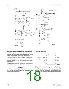
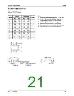
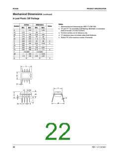
Mechanical Dimensions
8-Lead SOIC Package
Notes:
Inches
Millimeters
Symbol
Notes
1. Dimensioning and tolerancing per ANSI Y14.5M-1982.
Min.
Max.
Min.
Max.
2. "D" and "E" do not include mold flash. Mold flash or
protrusions shall not exceed .010 inch (0.25mm).
A
.053
.004
.013
.008
.189
.150
.069
.010
.020
.010
.197
.158
1.35
0.10
0.33
0.20
4.80
3.81
1.75
0.25
0.51
0.25
5.00
4.01
A1
B
3. "L" is the length of terminal for soldering to a substrate.
4. Terminal numbers are shown for reference only.
5. "C" dimension does not include solder finish thickness.
6. Symbol "N" is the maximum number of terminals.
C
D
E
5
2
2
e
.050 BSC
1.27 BSC
H
h
.228
.010
.016
.244
.020
.050
5.79
0.25
0.40
6.20
0.50
1.27
L
3
6
N
α
8
8
0°
8°
0°
8°
ccc
—
.004
—
0.10
8
5
E
H
1
4
h x 45°
D
C
A1
A
α
SEATING
PLANE
– C –
L
e
LEAD COPLANARITY
ccc C
B
REV. 1.2.1 6/14/01
21

 FAIRCHILD [ FAIRCHILD SEMICONDUCTOR ]