RC4200
PRODUCT SPECIFICATION
+VREF
300K
200K
60K
300K
100K
100K
167K
5
100K
5
100K
100K
VIN
8
7
8
7
13.3K
µ
22
F
RC4200A
Multiplier
RC4200A
Multiplier
10K
1
50K
1
X2
X
100K
250K*
44.4K**
50K
60K
4
4
VOUT
2
2
3
6
3
6
1/2
RC5532
-VS
-VS
83.3K
1/2
RC5532
µ
F
0.1
µ
F
0.1
80K
+VS
15K
+VS
30K
45.5 K
100
10K
30K
10K
100
-VS
*Determines sacle factor (K) for X2 function.
**Determines sacle factor (K) for function.
-VS
X
65-1869
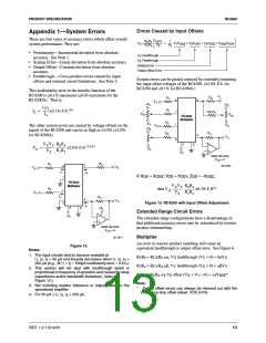
+V = +VREF = +15V
s
s
-V = -15V
2
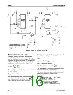
Figure 15. RMS to DC Converter V =√V
OUT IN
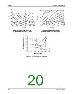
If V is made proportional to the average value of Asinωt
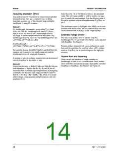
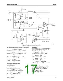
Amplitude Modulator with A.G.C.
H
(i.e., 2A/π) and scaled by a value of π/2 then:
In many AC modulator applications, unwanted output
modulation is caused by variations in carrier input ampli-
tude. The versatility of the RC4200 multiplier can be utilizes
to eliminate this undesired fluctuation. The extended range
multiplier circuit (Figure 4) shows an output amplitude
V =A
H
and if: V = Modulating input (V )
X
M
inversely proportional to the reference voltage V
.
REF
and: V Carrier input (Asinωt)
Y
R0Rd
VXVY R0Rd
-------------
R1R2
Then: V = K V sinωt where K =
0
M
--------------- -------------
=
i.e., V0
VREF R1R2
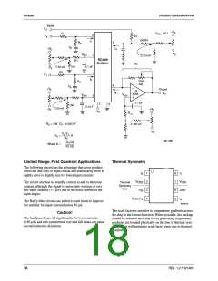
The resistor scaling is determined by the dynamic range of
the carrier variation and modulating input.
By making V
REF
proportional to V (where V is the car-
Y Y
rier input) such that:
The resistor values are solved, as with the other extended
range circuits, in terms of the input voltages.
VREF = VH ( VY
=
)
∫
Input voltages:
Then the denominator becomes a variable value that auto-
matically provides constant gain, such that the modulating
Modulation voltage (V ): 0 ≤ V ≤ V (max.)
M
M
X
Carrier (V ): V = Asinωt
Y
Y
input (V ) modulates the carrier (V ) with a fixed scale
X
Y
Carrier amplitude fluctuation (∆A):
factor even though the carrier varies in amplitude.
A(min.) sint ≤ V ≤ A(max.) sinΩωt
Y
Dynamic Range (N): A(max.)/A(min.),
A(max.) = V (max.) and A(min.) = V (min.)
H
H
16
REV. 1.2.1 6/14/01

 FAIRCHILD [ FAIRCHILD SEMICONDUCTOR ]