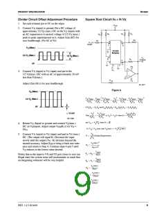
PRODUCT SPECIFICATION
RC4200
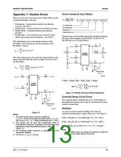
Errors Caused by Input Offsets
Appendix 1—System Errors
There are four types of accuracy errors which affect overall
system performance. They are:
R R
V
V
V
Z
1
V
Z
0
4
4
X
Y
V
=
V
V
V
V
V V
V V
OSX OSY
0
Y
OSX
X
OSY
0
OSZ
R R
0
• Nonimearity—Incremental deviation from absolute
accuracy. See Note 1.
• Scaling Error—Linear deviation from absolute accuracy.
• Output Offset—Constant deviation from absolute
accuracy.
V
V
Feedthrough
Feedthrough
Y
X
Scaling Error
Output Offset Error
• Feedthrough.—Cross-product errors caused by input
offsets and external circuit limitations. See Note 2.
System errors can be greatly reduced by externally trimming
the input offset voltages of the RC4200. ( 3.0% F.S. for
RC4200 and 0.1% for RC4200A.)
This nonlinearity error in the transfer function of the
RC4200 is 0.1% maximum ( 0.03 maximum for the
RC4200A). That is,
VZ
R
R
4
1
8
7
5
VX
+VS
+VS
I1I2
---------
0.1% F.S.(4)
R
1
I3
=
100 R
4
I4
XOS
ZOS
RC4200
Multiplier
R
2
-VS
1
2
-VS
VY
The other system errors are caused by voltage offsets on the
inputs of the RC4200 and can be as high as 3.0% ( 2.0%
for RC4200A).
+VS
RO
R
2
4
VO
VXVY R0R4
--------------- -------------
3
6
V0
=
3.0% F.S.(3)(4)
-VS
VZ R1R2
-VS
Ideal Op-Amp
VOS = 0
R
R
1
4
5
65-1870
8
VZ
VX
I
I
1
4
If X
OS
= X , Y
OSX OS
= Y
, Z
= -V ,
OSZ
OSY OS
7
RC4200
Multiplier
VXVY R0R4
(3)
R
2
--------------- -------------
VZ R1R2
then VO
0.3% F.S.
1
VY
I
RO
2
4
VO
2
Figure 13. RC4200 with Input Offset Adjustment
I
3
3
6
+VS
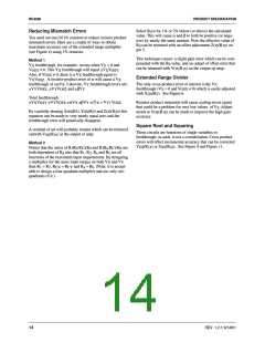
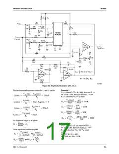
Extended Range Circuit Errors
-VS
The extended range configurations have a disadvantage in
that additional accuracy errors may be introduced by resistor
product mismatching.
Ideal Op-Amp
VOS = 0
Multiplier
65-1871
An error in resistor product matching will cause an
equivalent feedthrough or output offset error. See Figure 6.
Figure 12.
Notes:
1. The input circuits tend to become unstable at
I , I , I < 50 µA and linearity decreases when I , I , I >
R R = R α, V feedthrough (V = 0) = IαV
R
1 b CX d X Y X
1
2
4
1 2 4
250 µA (e.g., @ I = I = 500µA nonlinearity error ≈ 0.5%).
1
2
R R = R
2 a
R
β, V feedthrough (V = 0) = βV
CY d Y X Y
2. This section will not deal with feedthrough which is
proportional to frequency of operation and caused by stray
capacitance and/or bandwidth limitations. (refer to
Figure 12.)
3. Not including resistor tolerance or output offset on the
operational amplifier.
R R = R R γ, V offset (V = V = 0) = γV *
a b REF
C d
0
X
Y
Note:
*
Output offset errors can always be trimmed out with the
output op amp offset adjust, VOS (R16).
4. For 50 µA ≤ I , I , I ≤ 250 µA.
1
2 4
REV. 1.2.1 6/14/01
13

 FAIRCHILD [ FAIRCHILD SEMICONDUCTOR ]