6.8 R/S FLIP FLOP (LATCH) BLOCK
R-S F/F (LATCH)
PG BLOCK
R-S FF
REMOTE
ON/OFF
Q
OVP
UVP
S
R
NOR
ON/OFF
DELAY
Start-up
NOR
Q
PG
generator
Delayed
REMOTE
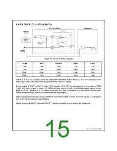
Figure 10. R-S F/F Block Diagram
OVP+
SET
RESET
Low
Qn+1
Qn
Qn+1
Qn
Low
Low
High
High
Low
Low
High
Low
High
Low
High
High
Low
High
Low
High
High
There is a R-S F/F (Latch) circuit for shutdown operation in the KA3511. R-S F/F (Latch) is con-
trolled by OVP, UVP, and some delayed remote ON/OFF signal.
If any output of OVP or UVP is High, SET signal of R-S F/F is high status and it produces PWM
“High” and main power is turned off. When remote signal is high, its delayed output signal is sup-
plied to RESET port of R-S F/F and it produces SET low. So output Q is low status. At this time,
PWM maintains high status by delayed remote high signal.
After main power is turned-off by OVP/UVP and initialized by remote, if remote signal is changed to
low, main power becomes operational.
When you test KA3511, Remote ON/OFF signal should be toggled once for initializing.
Rev C, November 1999
15

 FAIRCHILD [ FAIRCHILD SEMICONDUCTOR ]