6.7 REMOTE ON/OFF & DELAY BLOCK
Ton
Toff
Vref
12
PWM
REM
5V
Ion
Rpull
Trem
5
B
C
2.2V
+
COMP
1.8V
Trem
0.1uF
0.6V
COMP6
Ion/Ioff
PG
Block
Q1
Q2
6
REM
Remote On/Off
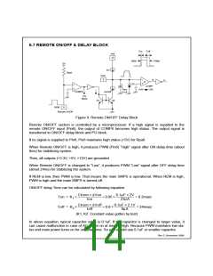
Figure 9. Remote ON/OFF Delay Block
Remote ON/OFF section is controlled by a microprocessor. If a high signal is supplied to the
remote ON/OFF input (Pin6), the output of COMP6 becomes high status. The output signal is
transferred to ON/OFF delay block and PG block.
If no signal is supplied to Pin6, Pin6 maintains high status (=5V) for Rpull.
When Remote ON/OFF is high, it produces PWM (Pin6) “High” signal after ON delay time (about
8ms) for stabilizing system.
Then, all outputs (+3.3V, +5V, +12V) are grounded.
When Remote ON/OFF is changed to “Low”, it produces PWM “Low” signal after OFF delay time
(about 24ms) for stabilizing the system.
If REM is low, then PWM is low. That means the main SMPS is operational. When REM is high,
PWM is high and the main SMPS is turned-off.
ON/OFF delay Time can be calculated by following equation.
× ∆
Ion
µ ×
µ
23 A
Ctrem
Von
0.1 F 2V
-----------------------------
×
0.95
--------------------------------------
=
=
×
×
≈
≈
Ton
Toff
K1
K2
= 8.2msec
= 24msec
× ∆
µ
8 A
×
µ
Ctrem
---------------------------------------
Ioff
Voff
0.1 F 2.1V
----------------------------------
×
0.8
(K1, K2: Constant value gotten by test)
In above equation, typical capacitor value is 0.1uF. If the capacitor is changed to larger value, it
can cause malfunction in case of AC power on at remote High. Because PWM maintains low sta-
tus and main power turns on for on delay time. So you should use 0.1uF or smaller capacitor.
Rev C, November 1999
14

 FAIRCHILD [ FAIRCHILD SEMICONDUCTOR ]