drops below -0.9V. This protection is latch mode and
reset when LVCC is pulled down below 5V.
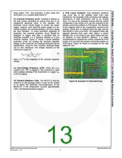
6. PCB Layout Guideline: Duty unbalance problems
may occur due to the radiated noise from main
transformer, the inequality of the secondary side leakage
inductances of main transformer, and so on. Among
them, it is one of the dominant reasons that the control
components in the vicinity of RT pin are enclosed by the
primary current flow pattern on PCB layout. The direction
of the magnetic field on the components caused by the
primary current flow is changed when the high and low
side MOSFET turns on by turns. The magnetic fields with
opposite direction from each other induce a current
through, into, or out of the RT pin, which makes the turn-
on duration of each MOSFET different. It is highly
recommended to separate the control components in the
vicinity of RT pin from the primary current flow pattern on
PCB layout. Figure 28 shows an example for the duty
balanced case.
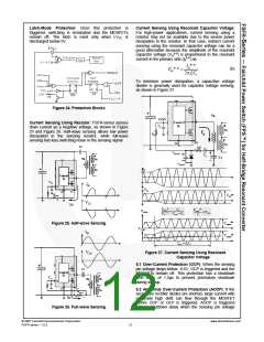
5.3 Overload Protection (OLP): Overload is defined as
the load current exceeding its normal level due to an
unexpected abnormal event. In this situation, the
protection circuit should trigger to protect the power
supply. However, even when the power supply is in the
normal condition, the overload situation can occur during
the load transition. To avoid premature triggering of
protection, the overload protection circuit should be
designed to trigger only after a specified time to
determine whether it is a transient situation or a true
overload situation. Figure 27 shows a typical overload
protection circuit. By sensing the resonant capacitor
voltage on the control pin, the overload protection can be
implemented. Using RC time constant, shutdown delay
can be also introduced. The voltage obtained on the
control pin is given as:
CB
p− p
(7)
VCON
=
VCr
2(CB + Csense
)
p-p
where VCr is the amplitude of the resonant capacitor
voltage.
5.4 Over-Voltage Protection (OVP): When the LVCC
reaches 23V, OVP is triggered. This protection is used
when auxiliary winding of the transformer to supply VCC
to FPS is utilized.
5.5 Thermal Shutdown (TSD): The MOSFETs and the
control IC in one package makes it easy for the control
IC to detect the abnormal over-temperature of the
MOSFETs. If the temperature exceeds approximately
130°C, the thermal shutdown triggers.
Figure 28. Example for Duty Balancing
© 2007 Fairchild Semiconductor Corporation
FSFR series • 1.0.3
www.fairchildsemi.com
13

 FAIRCHILD [ FAIRCHILD SEMICONDUCTOR ]