Lower arms
control input
c6
c7
Protection
SET
RESET
circuit state
Internal IGBT
c4
c3
Gate-Emitter Voltage
c2
SC
c1
c8
Output Current
SC Reference Voltage
Sensing Voltage
of the shunt
resistance
CR circuit time
constant delay
c5
Fault Output Signal
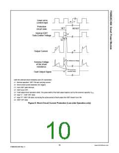
(with the external shunt resistance and CR connection)
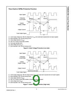
c1 : Normal operation: IGBT ON and carrying current.
c2 : Short circuit current detection (SC trigger).
c3 : Hard IGBT gate interrupt.
c4 : IGBT turns OFF.
c5 : Fault output timer operation starts: The pulse width of the fault output signal is set by the external capacitor CFO
.
c6 : Input “L” : IGBT OFF state.
c7 : Input “H”: IGBT ON state, but during the active period of fault output the IGBT doesn’t turn ON.
c8 : IGBT OFF state
Figure 8. Short-Circuit Current Protection (Low-side Operation only)
10
www.fairchildsemi.com
FSBB20CH60 Rev. C

 FAIRCHILD [ FAIRCHILD SEMICONDUCTOR ]