Typical Performance Characteristics
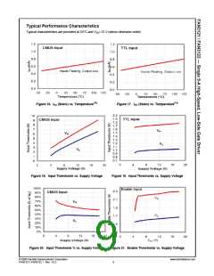
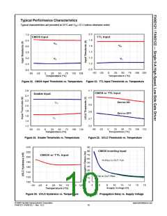
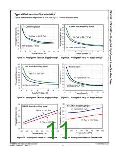
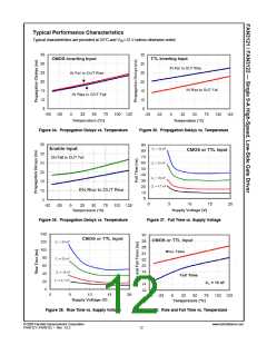
Typical characteristics are provided at 25°C and VDD=12 V unless otherwise noted.
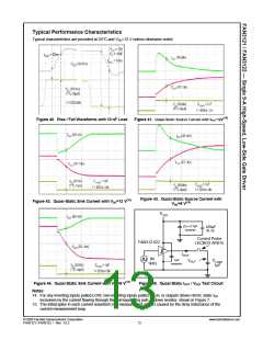
Figure 40. Rise / Fall Waveforms with 10 nF Load
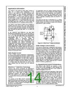
Figure 41. Quasi-Static Source Current with VDD=12V(15)
Figure 43. Quasi-Static Source Current with
VDD=8 V(15)
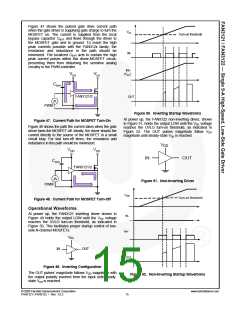
Figure 42. Quasi-Static Sink Current with VDD=12 V(15)
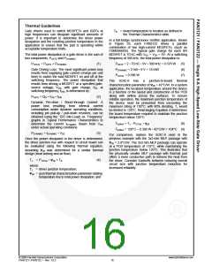
VDD
(2) x 4.7µF
470µF
ceramic
Al. El.
Current Probe
LECROY AP015
FAN3121/22
IOUT
IN
1kHz
1µF
ceramic
CLOAD
1µF
VOUT
Figure 44. Quasi-Static Sink Current with VDD=8 V(15)
Notes:
Figure 45. Quasi-Static IOUT / VOUT Test Circuit
14. For any inverting inputs pulled LOW, non-inverting inputs pulled HIGH, or outputs driven HIGH; static IDD
increases by the current flowing through the corresponding pull-up/down resistor, shown in Figure 7.
15. The initial spike in each current waveform is a measurement artifact caused by the stray inductance of the
current-measurement loop.
© 2008 Fairchild Semiconductor Corporation
FAN3121 / FAN3122 • Rev. 1.0.2
www.fairchildsemi.com
13

 FAIRCHILD [ FAIRCHILD SEMICONDUCTOR ]