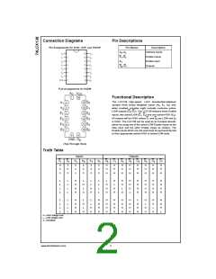
Connection Diagrams
Pin Descriptions
Pin Assignments for SOIC, SOP, and TSSOP
Pin Names
A0–A2
Description
Address Inputs
Enable Inputs
Enable Input
Outputs
E1–E2
E3
O0–O7
Pad Assignments for DQFN
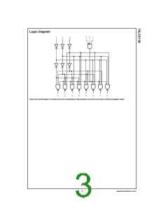
Functional Description
The LCX138 high-speed 1-of-8 decoder/demultiplexer
accepts three binary weighted inputs (A0, A1, A2) and,
when enabled, provides eight mutually exclusive active-
LOW outputs (O0–O7). The LCX138 features three Enable
inputs, two active-LOW (E1, E2) and one active-HIGH (E3).
All outputs will be HIGH unless E1 and E2 are LOW and E3
is HIGH. The LCX138 can be used as an 8-output demulti-
plexer by using one of the active LOW Enable inputs as the
data input and the other Enable inputs as strobes. The
Enable inputs which are not used must be permanently tied
to their appropriate active-HIGH or active-LOW state.
(Top Through View)
Truth Table
Inputs
Outputs
E1
E2
E3
A0
A1
A2
O0
O1
O2
O3
O4
O5
O6
O7
H
X
X
X
H
X
X
X
L
X
X
X
X
X
X
X
X
X
H
H
H
H
H
H
H
H
H
H
H
H
H
H
H
H
H
H
H
H
H
H
H
H
L
L
L
L
L
L
L
L
H
H
H
H
L
H
L
L
L
L
L
L
L
L
H
H
H
H
L
H
H
L
H
H
H
L
H
H
H
H
H
H
H
H
H
H
H
H
H
H
H
H
H
H
H
H
H
H
L
L
L
L
L
L
L
L
H
H
H
H
L
H
L
L
L
H
H
H
H
H
H
H
H
H
H
H
H
H
H
H
H
H
H
H
H
L
H
H
H
H
L
H
H
L
H
H
H
L
H
H
H
H
H
H
H = HIGH Voltage Level
L = LOW Voltage Level
X = Immaterial
www.fairchildsemi.com
2

 FAIRCHILD [ FAIRCHILD SEMICONDUCTOR ]