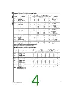
DC Electrical Characteristics for ACT
VCC
T
A = +25°C
TA = −40°C to +85°C
Symbol
VIH
Parameter
Units
Conditions
(V)
4.5
5.5
4.5
5.5
4.5
5.5
Typ
1.5
Guaranteed Limits
Minimum HIGH Level
Input Voltage
2.0
2.0
2.0
0.8
0.8
4.4
5.4
V
V
OUT = 0.1V
or VCC − 0.1V
OUT = 0.1V
or VCC − 0.1V
1.5
2.0
0.8
0.8
4.4
5.4
VIL
Maximum LOW Level
Input Voltage
1.5
V
V
V
V
V
V
1.5
VOH
Minimum HIGH Level
Output Voltage
4.49
5.49
I
OUT = −50 µA
V
IN = VIL or VIH
4.5
5.5
4.5
5.5
3.86
4.86
0.1
3.76
4.76
0.1
I
OH = −24 mA
I
OH = −24 mA (Note 5)
VOL
Maximum LOW Level
Output Voltage
0.001
0.001
I
OUT = 50 µA
0.1
0.1
V
IN = VIL or VIH
4.5
5.5
0.36
0.36
0.44
0.44
I
OL = 24 mA
I
OL = 24 mA (Note 5)
IIN
Maximum Input
Leakage Current
Maximum
5.5
5.5
±0.1
±1.0
µA
VI = VCC, GND
VI = VCC − 2.1V
ICCT
0.6
1.5
mA
ICC/Input
IOLD
IOHD
ICC
Minimum Dynamic
Output Current (Note 6)
Maximum Quiescent
Supply Current
5.5
5.5
75
mA
mA
V
V
V
OLD = 1.65V Max
OHD = 3.85V Min
IN = VCC
−75
5.5
4.0
40.0
µA
or GND
Note 5: All outputs loaded; thresholds on input associated with output under test.
Note 6: Maximum test duration 2.0 ms, one output loaded at a time.
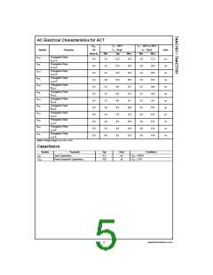
AC Electrical Characteristics for AC
VCC
T
A = +25°C
TA = −40°C to +85°C
C
L = 50 pF
C
L = 50 pF
Max
Symbol
Parameter
(V)
(Note 7)
3.3
Units
Min
Typ
11.5
8.5
12.0
8.5
8.0
6.0
8.5
6.5
9.5
7.0
9.5
7.0
Max
18.0
13.0
18.0
13.0
13.0
10.0
13.0
10.0
14.0
10.5
15.0
11.0
Min
3.0
2.0
2.5
1.5
2.0
1.5
1.5
1.5
2.0
1.5
2.0
1.5
tPLH
Propagation Delay
3.0
2.5
2.5
2.0
2.5
2.0
1.5
1.5
2.5
1.5
2.5
1.5
20.0
15.0
20.0
15.0
14.0
11.0
14.0
11.0
15.5
11.0
16.0
12.0
ns
ns
ns
ns
ns
ns
Sn to Z or Z
5.0
tPHL
tPLH
tPHL
tPLH
tPHL
Propagation Delay
Sn to Z or Z
3.3
5.0
Propagation Delay
E to Z or Z
3.3
5.0
Propagation Delay
E to Z or Z
3.3
5.0
Propagation Delay
In to Z or Z
3.3
5.0
Propagation Delay
3.3
In to Z or Z
5.0
Note 7: Voltage Range 3.3 is 3.3V ± 0.3V
Voltage Range 5.0 is 5.0V ± 0.5V
www.fairchildsemi.com
4

 FAIRCHILD [ FAIRCHILD SEMICONDUCTOR ]