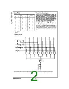
Truth Table
Functional Description
The AC/ACT151 is a logic implementation of a single pole,
8-position switch with the switch position controlled by the
state of three Select inputs, S0, S1, S2. Both true and com-
Inputs
Outputs
S2
S1
S0
E
H
L
L
L
L
L
L
L
L
Z
Z
L
plementary outputs are provided. The Enable input (E) is
active LOW. When it is not activated, the complementary
output is HIGH and the true output is LOW regardless of all
other inputs. The logic function provided at the output is:
X
L
X
L
X
L
H
I0
I1
I2
I3
I4
I5
I6
I7
I0
I1
I2
I3
I4
I5
I6
I7
L
L
H
L
Z = E • (I0 • S0 • S1 • S2 + I1 • S0 • S1 • S2
+
L
H
H
L
I2 • S0 • S1 • S2 + I3 • S0 • S1 • S2 + I4 • S0 • S1 • S2 + I5
S0 • S1 • S2 + I6 • S0 • S1 • S2 + I 7 • S0 • S1 • S2)
•
L
H
L
The AC/ACT151 provides the ability, in one package, to
select from eight sources of data or control information. By
proper manipulation of the inputs, the AC/ACT151 can pro-
vide any logic function of four variables and its comple-
ment.
H
H
H
H
L
H
L
H
H
H
H = HIGH Voltage Level
L = LOW Voltage Level
X = Immaterial
Logic Diagram
Please note that this diagram is provided only for the understanding of logic operations and should not be used to estimate propagation delays.
www.fairchildsemi.com
2

 FAIRCHILD [ FAIRCHILD SEMICONDUCTOR ]