XRT86L30
SINGLE T1/E1/J1 FRAMER/LIU COMBO
REV. 1.0.1
14.2
The E1 Multi-frame Structure
There are two types of E1 Multi-frame structures, CRC Multi-frame and CAS Multi-frame. The CAS Multi-
frame can be considered a subset of the CRC Multi-frame, in that CAS is an option to carry signaling
information within the CRC Multi-frame structure.
14.2.1
The CRC Multi-frame Structure
A CRC Multi-frame consists of 16 consecutive E1 frames, with the first of these frames being a FAS frame.
From a Frame Alignment point of view, timeslot 0 of each of these E1 frames within the Multi-frame are the
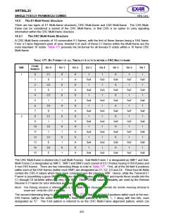
most important 16 octets. Table 177 presents the bit-format for all timeslot 0 octets within a 16 frame CRC
Multi-frame.
TABLE 177: BIT FORMAT OF ALL TIMESLOT 0 OCTETS WITHIN A CRC MULTI-FRAME
F
RAME
SMF
B
IT
0
B
IT
1
B
IT
2
B
IT
3
B
IT
4
B
IT
5
B
IT
6
B
IT
7
N
UMBER
1
0
C1
0
0
1
0
1
0
1
0
1
0
1
0
1
0
1
0
1
0
A
0
1
1
0
1
1
1
Sa4
1
Sa5
1
Sa6
0
Sa7
1
Sa8
1
2
C2
0
3
A
0
Sa4
1
Sa5
1
Sa6
0
Sa7
1
Sa8
1
4
C3
1
5
A
0
Sa4
1
Sa5
1
Sa6
0
Sa7
1
Sa8
1
6
C4
0
7
A
0
Sa4
1
Sa5
1
Sa6
0
Sa7
1
Sa8
1
2
8
C1
1
9
A
0
Sa4
1
Sa5
1
Sa6
0
Sa7
1
Sa8
1
10
11
12
13
14
15
C2
1
A
0
Sa4
1
Sa5
1
Sa6
0
Sa7
1
Sa8
1
C3
E
A
0
Sa4
1
Sa5
1
Sa6
0
Sa7
1
Sa8
1
C4
E
A
Sa4
Sa5
Sa6
Sa7
Sa8
The CRC Multi-frame is divided into 2 sub Multi-Frames. Sub-Multi-Frame 1 is designated as SMF1 and Sub-
Multi-Frame 2 is designated as SMF2. SMF1 and SMF2 each consist of 8 E1 frames having 4 FAS frames and
4 non-FAS frames. There are two interesting things to note in Table 177. First, all of the bit-field 0 positions
within each of the FAS frames (within each SMF) are designated as C1, C2, C3 and C4. These four bit-fields
contain the CRC-4 values which have been computed over the previous SMF. Hence, while the Transmit E1
Framer is assembling a given SMF, it computes the CRC-4 value for that SMF and inserts these results into the
C1 through C4 bit-fields within the very next SMF. These CRC-4 values ultimately are used by the Remote
Receive E1 Framer for error detection purposes.
NOTE: This framing structure is referred to as a CRC Multi-Frame because it permits the remote receiving terminal to
locate and verify the CRC-4 bit-fields.
The second interesting thing to note regarding Table 177 is that the bit-field 0 positions within each of the non-
FAS frames (within the entire MF) are of a fixed 6-bit pattern 0, 0, 1, 0, 1, 1 along with two bits, each
designated as “E”. This 6-bit pattern is referred to as the CRC Multi-Frame alignment pattern, which can
251

 EXAR [ EXAR CORPORATION ]