XRT86L30
REV. 1.0.1
SINGLE T1/E1/J1 FRAMER/LIU COMBO
14.1.2
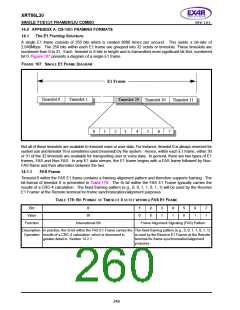
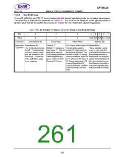
Non-FAS Frame
Timeslot 0 within the non-FAS E1 frame contains bits that support signaling or data link message transmission.
The bit-format of timeslot 0 is presented in Table 176. The Si bit in the Non-FAS frame typically carries a
specific value that will be used by the Receive E1 Framer for CRC Multi-frame alignment purposes.
TABLE 176: BIT
F
ORMAT OF
TIMESLOT 0 OCTET WITHIN A NON-FAS E1 FRAME
B
IT
0
Si
1
2
3
4
5
6
7
Value
1
A
Sa4 Sa5 Sa6 Sa7 Sa8
National bits
Function6
International Bit
Fixed Value
Yellow Alarm
Description- International Bit
Fixed at “1”
FAS Frame Yellow Alarm Bit National Bits
Operation
The Si bit within the non- Bit-field “1” contains a This bit-field is used to
These bit-fields can be
used to carry data link
FAS E1 Frame typically
carries a specific value
that will be used by the
Receive E1 Framer for
CRC Multi-frame align-
ment purposes.
fixed value “1”. This bit- transmit a Yellow alarm to
field will be used for
FAS framing synchroni- bit-field is set to “0” during
the Remote Terminal. This information from the Local
transmitting terminal to
zation/alignment pur-
poses by the Remote
Receive E1 Framer.
normal conditions, and is set the Remote receiving ter-
to “1” whenever the Receive minal. Since the National
E1 Framer detects an LOS bits only exist in the non-
(Loss of Signal) or LOF
FAS frames, they offer a
(Loss of Framing) condition maximum signaling data
in the incoming E1 frame
data.
link bandwidth of 20kbps.
250

 EXAR [ EXAR CORPORATION ]