XRT86L30
REV. 1.0.1
SINGLE T1/E1/J1 FRAMER/LIU COMBO
Transmit Yellow Alarm in SF Mode
12.6.4
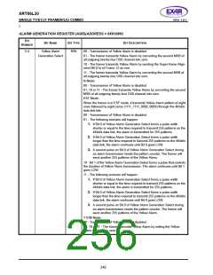
In SF mode, the XRT86L30 supports transmission of Yellow Alarm in two ways. When the Yellow Alarm
Generation Select bits of the Alarm Generation Register are set to 01 or 11, the second MSB of all DS0
channels is transmitted as zero. This is Yellow Alarm for DS1 standard.
When the Yellow Alarm Generation Select bits of the Alarm Generation Register are set to 10, the Framing bit
of Frame 12 is transmitted as one. This is Yellow Alarm for J1 standard.
12.6.5
Transmit Yellow Alarm in ESF Mode
In ESF mode, the XRT86L30 transmits Yellow Alarm on the 4Kbit/s data link channel. The Facility Data Link
bits are sent in the pattern of eight ones followed by eight zeros. The number of repetitions of this pattern
depends on the duration of Yellow Alarm Generation Select bits of the Alarm Generation Register. When these
select bits are set to 01 or 11, the following scenario will happen:
1. If Bit 0 of Yellow Alarm Generation Select forms a pulse width shorter or equal to the time required to trans-
mit 255 patterns on the 4Kbit/s data link, the alarm is transmitted for 255 patterns.
2. If Bit 0 of Yellow Alarm Generation Select forms a pulse width longer than the time required to transmit 255
patterns on the 4Kbit/s data link, the alarm continues until Bit 0 goes LOW.
3. A second pulse on Bit 0 of Yellow Alarm Generation Select during an alarm transmission resets the pattern
counter. The framer will send another 255 patterns of the Yellow Alarm.
NOTE: To pulse Bit 0, this bit must be programmed to “1” and then reset back to “0”. The pulse width is the duration in time
that this bit remains at “1”.
When these select bits are set to 10, Bit 1 of the Yellow Alarm Generation Select forms a pulse that controls the
duration of Yellow Alarm transmission. The alarm continues until Bit 1 goes LOW.
When these select bits are set to 01, the following scenario will happen:
1. If Bit 0 of Yellow Alarm Generation Select forms a pulse width shorter or equal to the time required to trans-
mit 255 patterns on the 4Kbit/s data link, the alarm is transmitted for 255 patterns.
2. If Bit 0 of Yellow Alarm Generation Select forms a pulse width longer than the time required to transmit 255
patterns on the 4Kbit/s data link, the alarm continues until Bit 0 goes LOW.
3. A second pulse on Bit 0 of Yellow Alarm Generation Select during an alarm transmission resets the pattern
counter. The framer will send another 255 patterns of the Yellow Alarm.
12.6.6
Transmit Yellow Alarm in N Mode
In N mode, when the Yellow Alarm Generation Select bits of the Alarm Generation Register are set to 01, 10 or
11, the second MSB of all DS0 channels is transmitted as zero.
12.6.7
Transmit Yellow Alarm in T1DM Mode
In T1DM mode, when the Yellow Alarm Generation Select bits of the Alarm Generation Register are set to 01,
10 or 11, the Yellow Alarm bit (the third LSB of Timeslot 23) is set to zero.The table below shows configurations
of the Yellow Alarm Generation Select bits of the Alarm Generation Register (AGR).
244

 EXAR [ EXAR CORPORATION ]