XRT86L30
SINGLE T1/E1/J1 FRAMER/LIU COMBO
REV. 1.0.1
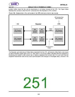
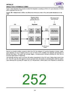
Figure below illustrates this scenario in which the Repeater is sending an AIS to CO upon detection of Yellow
alarm originated from the CPE.
FIGURE 105. GENERATION OF AIS BY THE
R
EPEATER UPON DETECTION OF
YELLOW
A
LARM ORIGINATED BY THE
CPE
Repeater detects
Yellow alarm and
generate AIS to CO
CPE declares Red
Alarm internally
CO
Repeater
CPE
Yellow
Alarm
AIS
DS1
Transmit
Section
DS1
Receive
Section
DS1 Receive
Framer Block
DS1 Receive
Framer Block
DS1
Receive
Section
DS1
Transmit
Section
DS1 Transmit
Framer Block
DS1 Transmit
Framer Block
The DS1 line is
broken
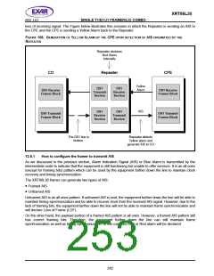
Now let us consider another scenario in which the DS1 line between CO and the Repeater is broken. Again,
upon detection of Loss of Signal (LOS) or Loss of Frame (LOF) condition, the Repeater will generate an
internal Red Alarm. This alarm will normally trigger a microprocessor interrupt informing the user that an
incoming signal failure is happening.
The Repeater will also send an all ones AIS pattern downstream to the CPE and a Yellow Alarm back to the
CO. The CPE uses the AIS signal to recover received clock and remain in synchronization with the system.
Upon detecting the incoming AIS signal, the CPE will generate a Yellow Alarm to the Repeater to indicate the
241

 EXAR [ EXAR CORPORATION ]