XRT86L30
SINGLE T1/E1/J1 FRAMER/LIU COMBO
REV. 1.0.1
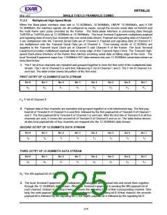
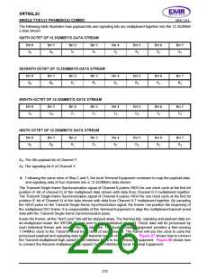
The following table illustrates how payload bits and signaling bits are multiplexed together into the 12.352Mbit/
s data stream.
SIXTH OCTET OF 12.352MBIT/S DATA STREAM
B
IT
0
B
IT
1
B
IT
2
B
IT
3
B
IT
4
4
4
4
B
IT
5
5
5
5
B
IT
6
6
6
6
B
IT
7
7
7
7
50
A0
51
A1
52
A2
53
A3
SEVENTH OCTET OF 12.352MBIT/S DATA STREAM
B
IT
0
B
IT
1
B
IT
2
B
IT
3
B
IT
B
IT
B
IT
B
IT
60
B0
61
B1
62
B2
63
B3
EIGHTH OCTET OF 12.352MBIT/S DATA STREAM
B
IT
0
B
IT
1
B
IT
2
B
IT
3
B
IT
B
IT
B
IT
B
IT
70
C0
71
C1
72
C2
73
C3
NINTH OCTET OF 12.352MBIT/S DATA STREAM
B
IT
0
B
IT
1
B
IT
2
B
IT
3
B
IT
B
IT
B
IT
B
IT
80
D0
81
D1
82
D2
83
D3
XY: The Xth payload bit of Channel Y
AY: The signaling bit A of Channel Y
4. Following the same rules of Step 2 and 3, the local Terminal Equipment continues to map the payload data
and signaling data of four channels into a 12.352Mbit/s data stream.
The Transmit Single-frame Synchronization signal of Channel 0 pulses HIGH for one clock cycle at the first bit
position (F-bit of channel 0) of the multiplexed data stream with data from Channel 0-3 multiplexed together.
The Transmit Single-frame Synchronization signal of Channel 4 pulses HIGH for one clock cycle at the first bit
position (F-bit of Channel 4) of the data stream with data from Channel 4-7 multiplexed together. By sampling
the HIGH pulse on the Transmit Single-frame Synchronization signal, the framer can position the beginning of
the multiplexed DS1 frame. It is responsibility of the Terminal Equipment to align the multiplexed transmit serial
data with the Transmit Single-frame Synchronization pulse.
Inside the framer, all the "don't care" bits will be stripped away. The framing bits, signaling and payload data are
de-multiplexed inside the XRT86L30 and sent to each individual channel. These data will be processed by
each individual framer and send to the LIU interface. The local Terminal Equipment provides a free-running
1.544MHz clock to the Transmit Serial Input clock of each channel. The framer will use this clock to carry the
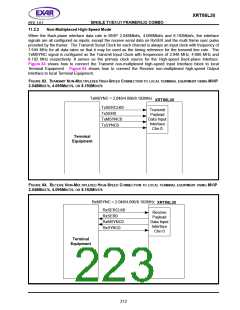
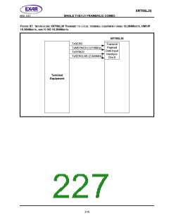
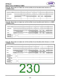
processed payload and signaling data to the transmit section of the device. Figure 87 shows how to connect
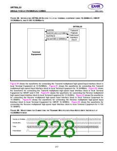
the Transmit multiplexed high-speed Input Interface block to local Terminal Equipment. Figure 88 shows how
to connect the Receive multiplexed high-speed Output Interface to local Terminal Equipment.
215

 EXAR [ EXAR CORPORATION ]