XRT86L30
REV. 1.0.1
SINGLE T1/E1/J1 FRAMER/LIU COMBO
Multiplexed High-Speed Mode
11.2.3
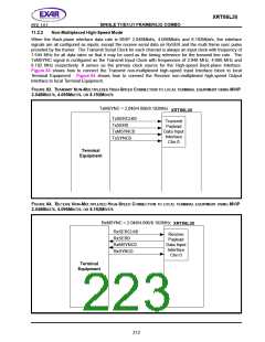
When the Back-plane interface data rate is 12.352Mbit/s, 16.384Mbit/s, HMVIP 16.384Mbit/s, and H.100
16.384Mbit/s, the interface signals are all configured as inputs, except the receive serial data on RxSER and
the multi frame sync pulse provided by the framer. The Back-plane Interface is processing data through
TxSER0 or TxSER4 pins at 12.352Mbit/s or 16.384Mbit/s. The local Terminal Equipment multiplexes payload
and signaling data of every four channels into one serial data stream. Payload and signaling data of Channel 0-
3 are multiplexed onto the Transmit Serial Data pin of Channel 0. Payload and signaling data of Channel 4-7
are multiplexed onto the Transmit Serial Data pin of Channel 4. Free-running clocks of 12.352MHz are
supplied to the Transmit Input Clock pin of Channel 0 and Channel 4 of the framer. The local Terminal
Equipment provides multiplexed payload data at rising edge of this Transmit Input Clock. The Transmit High-
speed Back-plane Interface of the framer then latches incoming serial data at falling edge of the clock. The
local Terminal Equipment maps four 1.544Mbit/s DS1 data streams into one 12.352Mbit/s serial data stream as
described below:
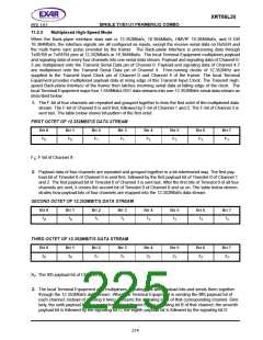
1. The F-bit of four channels are repeated and grouped together to form the first octet of the multiplexed data
stream. The F-bit of Channel 0 is sent first, followed by F-bit of Channel 1 and 2. The F-bit of Channel 3 is
sent last. The table below shows bit-pattern of the first octet.
FIRST OCTET OF 12.352MBIT/S DATA STREAM
B
IT
0
B
IT
1
B
IT
2
B
IT
3
B
IT
4
B
IT
5
B
IT
6
BIT 7
F0
F0
F1
F1
F2
F2
F3
F3
FX: F-bit of Channel X
2. Payload data of four channels are repeated and grouped together in a bit-interleaved way. The first pay-
load bit of Timeslot 0 of Channel 0 is sent first, followed by the first payload bit of Timeslot 0 of Channel 1
and 2. The first payload bit of Timeslot 0 of Channel 3 is sent last. After the first bits of Timeslot 0 of all four
channels are sent, it comes the second bit of Timeslot 0 of Channel 0 and so on. The table below demon-
strates how payload bits of four channels are mapped into the 12.352Mbit/s data stream.
SECOND OCTET OF 12.352MBIT/S DATA STREAM
B
IT
0
B
IT
1
B
IT
2
B
IT
3
B
IT
4
B
IT
5
B
IT
6
B
IT
7
10
10
11
11
12
12
13
13
THIRD OCTET OF 12.352MBIT/S DATA STREAM
B
IT
0
B
IT
1
B
IT
2
B
IT
3
B
IT
4
B
IT
5
B
IT
6
B
IT
7
20
20
21
21
22
22
23
23
XY: The Xth payload bit of Channel Y
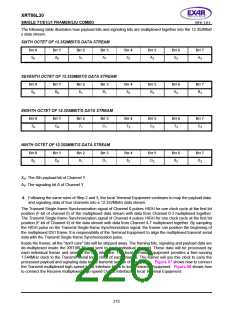
3. The local Terminal Equipment also multiplexes signaling bits with payload bits and sends them together
through the 12.352Mbit/s data stream. When the Terminal Equipment is sending the fifth payload bit of
each channel, instead of sending it twice, it inserts the signaling bit A of that corresponding channel. Simi-
larly, the sixth payload bit of a each channel is followed by the signaling bit B of that channel; the seventh
payload bit is followed by the signaling bit C; the eighth payload bit is followed by the signaling bit D.
214

 EXAR [ EXAR CORPORATION ]