XRT86L30
SINGLE T1/E1/J1 FRAMER/LIU COMBO
9.0 LIU RECEIVE PATH
REV. 1.0.1
9.1
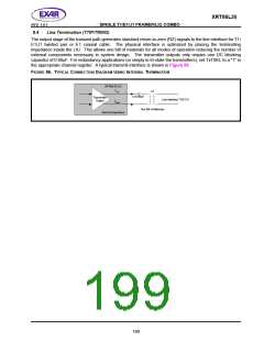
Line Termination (RTIP/RRING)
9.1.1
CASE 1: Internal Termination
The input stage of the receive path accepts standard T1/E1/J1 twisted pair or E1 coaxial cable inputs through
RTIP and RRING. The physical interface is optimized by placing the terminating impedance inside the LIU.
This allows one bill of materials for all modes of operation reducing the number of external components
necessary in system design. The receive termination impedance is selected by programming TERSEL[1:0] to
match the line impedance. Selecting the internal impedance is shown in Table 172.
T
ABLE 172: SELECTING THE
I
NTERNAL
I
MPEDANCE
ERMINATION
TERSEL[1:0]
0h (00)
R
ECEIVE T
100
Ω
Ω
1h (01)
110
2h (10)
75Ω
3h (11)
120
Ω
The XRT86L30 has the ability to switch the internal termination to "High" impedance by programming RxTSEL
in the appropriate channel register, if the RxTSEL hardware pin is “High”. For internal termination, set RxTSEL
to "1". By default, RxTSEL is set to "0" ("High" impedance). For redundancy applications, a dedicated
hardware pin (RxTSEL) is available to control the receive termination for all channels simultaneously. This
hardware pin is AND-ed with the register bit. Both, the register bit and the hardware pin must be set active for
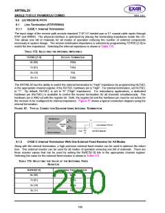
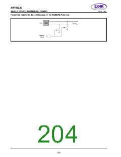
the receiver to be configured for internal impedance. Figure 57 shows a typical connection diagram using the
internal termination.
F
IGURE 57. TYPICAL
C
ONNECTION
D
IAGRAM
U
SING
INTERNAL TERMINATION
XRT86L30 LIU
RTIP
1:1
Receiver
Input
Line Interface T1/E1/J1
RRING
0.1µF
One Bill of Materials
Internal Impedance
9.1.2
CASE 2: Internal Termination With One External Fixed Resistor for All Modes
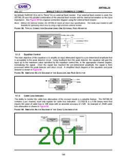
Along with the internal termination, a high precision external fixed resistor can be used to optimize the return
loss. This external resistor can be used for all modes of operation ensuring one bill of materials. There are
three resistor values that can be used by setting the RxRES[1:0] bits in the appropriate channel register.
Selecting the value for the external fixed resistor is shown in Table 173.
TABLE 173: SELECTING THE
VALUE OF THE EXTERNAL FIXED
R
ESISTOR
R
X
RES[1:0]
EXTERNAL FIXED RESISTOR
0h (00)
1h (01)
2h (10)
3h (11)
None
240
210
150
Ω
Ω
Ω
189

 EXAR [ EXAR CORPORATION ]