XRT86L30
SINGLE T1/E1/J1 FRAMER/LIU COMBO
REV. 1.0.1
7.5.2
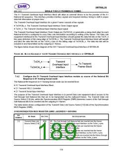
Configure the E1 Receive Overhead Output Interface module as source of the National Bit
Sequence in E1 framing format mode
The National Bit Sequence in E1 framing format mode can be extracted and directed to:
•
•
•
E1 Receive Overhead Output Interface Block
E1 Receive HDLC Controller
E1 Receive Serial Output Interface
The purpose of the Receive Overhead Output Interface is to permit Data Link equipment to have direct access
to the Sa4 through Sa8 National bits that are extracted from the incoming E1 frames. Independent of the
availability of the E1 Receive HDLC Controller module, the XRT86L30 always output the received National bits
through the Receive Overhead Output Interface block.
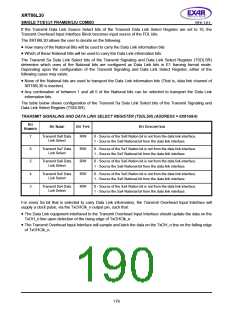
The XRT86L30 allows the user to decide on the following:
•
•
How many of the National Bits is used to carry the Data Link information bits
Which of these National Bits is used to carry the Data Link information bits.
The Receive Sa Data Link Select bits of the Receive Signaling and Data Link Select Register (TSDLSR)
determine which ones of the National bits are configured as Data Link bits in E1 framing format mode.
Depending upon the configuration of the Receive Signaling and Data Link Select Register, either of the
following cases may exists:
•
None of the received National bits are used to transport the Data Link information bits (That is, data link
channel of XRT86L30 is inactive).
•
Any combination of between 1 and all 5 of the received National bits are used to transport the Data Link
information bits.
The table below shows configuration of the Receive Sa Data Link Select bits of the Receive Signaling and Data
Link Select Register (RSDLSR).
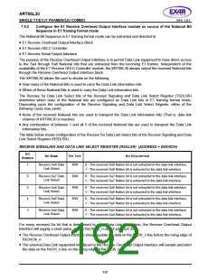
RECEIVE SIGNALING AND DATA LINK SELECT REGISTER (RSDLSR) (ADDRESS = 0X010CH)
B
IT
B
IT
N
AME
B
IT
TYPE
BIT DESCRIPTION
N
UMBER
7
Receive Sa8 Data
Link Select
R/W
R/W
R/W
R/W
R/W
0 - The received Sa8 Nation bit is not extracted to the data link interface.
1 - The received Sa8 Nation bit is extracted to the data link interface.
6
5
4
3
Receive Sa7 Data
Link Select
0 - The received Sa7 Nation bit is not extracted to the data link interface.
1 - The received Sa7 Nation bit is extracted to the data link interface.
Receive Sa6 Data
Link Select
0 - The received Sa6 Nation bit is not extracted to the data link interface.
1 - The received Sa6 Nation bit is extracted to the data link interface.
Receive Sa5 Data
Link Select
0 - The received Sa5 Nation bit is not extracted to the data link interface.
1 - The received Sa5 Nation bit is extracted to the data link interface.
Receive Sa4 Data
Link Select
0 - The received Sa4 Nation bit is not extracted to the data link interface.
1 - The received Sa4 Nation bit is extracted to the data link interface.
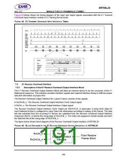
For every received Sa bit that is determined to carry Data Link information, the Receive Overhead Output
Interface will supply a clock pulse, via the RxOHClk_n output pin, such that:
•
The Receive Overhead Output interface should update the data on the RxOH_n line before the rising edge of
RxOHClk_n.
•
The external Data Link equipment interfaced to the Receive Overhead Output Interface will sample and latch
the data on the RxOH_n line on the rising edge of RxOHClk_n.
181

 EXAR [ EXAR CORPORATION ]