xr
XR16L2552
2.25V TO 5.5V DUART WITH 16-BYTE FIFO
REV. 1.1.1
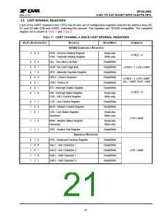
3.0 UART INTERNAL REGISTERS
Each of the UART channel in the L2552 has its own set of configuration registers selected by address lines A0,
A1 and A2 with CS# and CHSEL selecting the channel. The registers are 16C550 compatible. The complete
register set is shown in Table 7 and Table 8.
TABLE 7: UART CHANNEL A AND B UART INTERNAL REGISTERS
A2,A1,A0 ADDRESSES
REGISTER
READ/WRITE
COMMENTS
LCR[7] = 0
16C550 COMPATIBLE REGISTERS
0
0 0
RHR - Receive Holding Register
Read-only
Write-only
THR - Transmit Holding Register
DLL - Div Latch Low Byte
DLM - Div Latch High Byte
AFR - Alternate Function Register
DREV - Device Revision
0
0 0
0 1
1 0
0 0
0 1
0 1
1 0
Read/Write
Read/Write
Read/Write
Read/Write
Read/Write
Read/Write
0
0
0
0
0
0
LCR[7] = 1, LCR ≠ 0xBF
LCR[7] = 1, LCR ≠ 0xBF,
DLL = 0x00, DLM = 0x00
DVID - Device ID
IER - Interrupt Enable Register
LCR[7] = 0
ISR - Interrupt Status Register
FCR - FIFO Control Register
Read-only
Write-only
0
1
1
1 1
0 0
0 1
LCR - Line Control Register
Read/Write
Read/Write
MCR - Modem Control Register
LSR - Line Status Register
Reserved
Read-only
Write-only
LCR ≠ 0xBF
1
1
1 0
1 1
MSR - Modem Status Register
Reserved
Read-only
Write-only
SPR - Scratch Pad Register
Read/Write
ENHANCED REGISTERS
0
1
1
1
1
1 0
0 0
0 1
1 0
1 1
EFR - Enhanced Function Register
Xon-1 - Xon Character 1
Xon-2 - Xon Character 2
Xoff-1 - Xoff Character 1
Xoff-2 - Xoff Character 2
Read/Write
Read/Write
Read/Write
Read/Write
Read/Write
LCR = 0xBF
21

 EXAR [ EXAR CORPORATION ]