XR-2206
Output Amplitude:
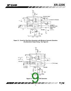
Maximum output amplitude is inversely proportional to
at Pin 1 is approximately 100kW. Output amplitude varies
the external resistor, R , connected to Pin 3 (see
linearly with the applied voltage at Pin 1, for values of dc
3
Figure 3). For sine wave output, amplitude is
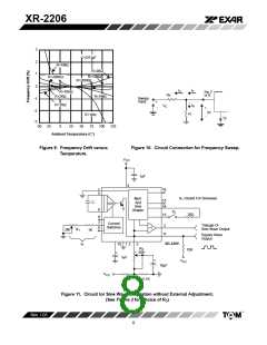
bias at this pin, within 14 volts of V /2 as shown in
CC
approximately 60mV peak per kW of R ; for triangle, the
Figure 6. As this bias level approaches V /2, the phase
3
CC
peak amplitude is approximately 160mV peak per kW of
of the output signal is reversed, and the amplitude goes
through zero. This property is suitable for phase-shift
keying and suppressed-carrier AM generation. Total
dynamic range of amplitude modulation is approximately
55dB.
R . Thus, for example, R = 50kW would produce
3
3
approximately 13V sinusoidal output amplitude.
Amplitude Modulation:
CAUTION: AM control must be used in conjunction with a
Output amplitude can be modulated by applying a dc bias
and a modulating signal to Pin 1. The internal impedance
well-regulated supply, since the output amplitude now becomes
a function of V
.
CC
VR
V
CC
11
15 V2
5
14 16 6
13
1
3 2
V
CC
7
6
5
8
10
V
CC
VR
V1
4
VR
V1
V2
Int’nI.
Reg.
VR
9
12
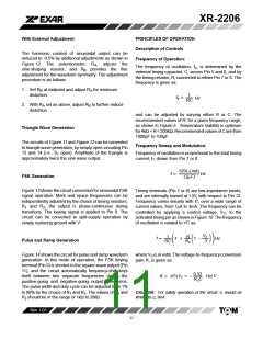
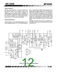
Figure 15. Equivalent Schematic Diagram
Rev. 1.03
12

 EXAR [ EXAR CORPORATION ]