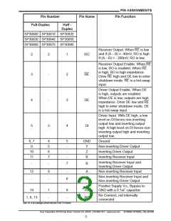
PIN ASSIGNMENTS
Pin Function
Pin Number
Full-Duplex
Pin Name
Half -
Duplex
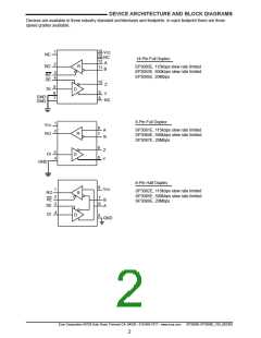
SP3080E SP3081E SP3082E
SP3083E SP3084E SP3085E
SP3086E SP3087E SP3088E
Receiver Output. When RE is low
and if (A – B) ≥ -40mV, RO is high.
If (A – B) ≤ - 200mV, RO is low.
2
2
1
RO
Receiver Output Enable. When RE
is low, RO is enabled. When RE
is high, RO is high impedance.
Drive RE high and DE low to enter
shutdown mode. RE is a hot-swap
input.
3
-
2
REREREE
Driver Output Enable. When DE
is high, outputs are enabled.
When DE is low, outputs are high
impedance. Drive DE low and RE
high to enter shutdown mode. DE
is a hot-swap input.
4
5
-
3
4
DE
DI
Driver Input. With DE high, a low
level on DI forces non-inverting
output low and inverting output
high. A high level on DI forces non-
inverting output high and inverting
output low.
3
6, 7
9
4
5
6
7
5
-
GND
Ground
Y
Z
B
Non-inverting Driver Output
Inverting Driver Output
Inverting Receiver Input
10
11
-
-
Inverting Receiver Input and
Inverting Driver Output
-
-
7
B
12
8
-
A
A
Non-inverting Receiver Input
Non-inverting Receiver Input and
Non-inverting Driver Output
-
-
6
Positive Supply VCC. Bypass to
14
1
8
VCC
GND with a 0.1uF capacitor.
No Connect, not internally
connected
1, 8, 13
-
-
NC
Note: On 14-pin packages connect both pins 6 and 7 to Ground.
Exar Corporation 48720 Kato Road, Fremont CA, 94538 • 510-668-7017 • www.exar.com
SP3080E-SP3088E_100_062309
3

 EXAR [ EXAR CORPORATION ]