Document No.: FT_000288
FT232H SINGLE CHANNEL HI-SPEED USB TO MULTIPURPOSE UART/FIFO IC
Datasheet Version 1.8
Clearance No.: FTDI #199
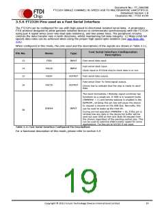
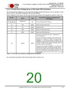
3.5.7 FT232H Pins Configured as a CPU-style FIFO Interface
The FT232H can be configured in a CPU-style FIFO interface mode which allows a CPU to interface to USB
via the FT232H. This mode is enabled in the external EEPROM.
When configured in this mode, the pins used and the descriptions of the signals are shown in Table 3.12
Pin No.
Fast Serial Interface Configuration
Description
Name
Type
13, 14, 15, 16,
17, 18, 19, 20
ADBUS[7:0]
I/O
D7 to D0 bidirectional data bus
21
25
26
27
CS#
A0
INPUT
INPUT
INPUT
INPUT
Active low chip select input
Address bit A0
RD#
WR#
Active Low FIFO Read input
Active Low FIFO Write input
Tie this pin to VCCIO if not used – otherwise, for
normal operation
The Send Immediate / WakeUp signal combines two
functions on a single pin. If USB is in suspend mode
(PWREN# = 1) and remote wakeup is enabled in the
EEPROM, strobing this pin low will cause the device to
request a resume on the USB Bus. Normally, this can
be used to wake up the Host PC.
28
SIWU#
INPUT
During normal operation (PWREN# = 0), if this pin is
strobed low any data in the device RX buffer will be
sent out over USB on the next Bulk-IN request from
the drivers regardless of the pending packet size. This
can be used to optimize USB transfer speed for some
applications.
Table 3.12 CPU-style FIFO Interface Configured Pin Descriptions
For a functional description of this mode, please refer to section 4.10
Copyright © 2012 Future Technology Devices International Limited
20

 ETC [ ETC ]