ZSPM1025A
True Digital PWM Controller (Single-Phase, Single-Rail)
4.7.8. STATUS_VOUT................................................................................................................................29
4.7.9. STATUS_IOUT .................................................................................................................................30
4.7.10. STATUS_INPUT ...............................................................................................................................30
4.7.11. STATUS_TEMPERATURE...............................................................................................................30
4.7.12. STATUS_CML ..................................................................................................................................31
4.7.13. STATUS_MFR_SPECIFIC ...............................................................................................................31
4.7.14. READ_VIN ........................................................................................................................................31
4.7.15. READ_VOUT ....................................................................................................................................31
4.7.16. READ_IOUT......................................................................................................................................32
4.7.17. READ_TEMPERATURE1.................................................................................................................32
4.7.18. READ_TEMPERATURE2.................................................................................................................32
Application Information...................................................................................................................................33
5.1. Typical Application Circuit .......................................................................................................................33
5.1.1. Output Voltage Selection ..................................................................................................................35
5.1.2. Output Capacitor Selection...............................................................................................................35
5.2. Typical Performance Measurements for the ZSPM1025A......................................................................35
5.2.1. Typical Load Transient Response – Capacitor Range #1 – VOUT Range #1 .................................36
5.2.2. Typical Load Transient Response – Capacitor Range #2 – VOUT Range #1 .................................37
5.2.3. Typical Load Transient Response – Capacitor Range #3 – VOUT Range #1 .................................38
5.2.4. Typical Load Transient Response – Capacitor Range #4 – VOUT Range #1 .................................39
5.2.5. Typical Load Transient Response – Capacitor Range #1 – VOUT Range #2 .................................40
5.2.6. Typical Load Transient Response – Capacitor Range #2 – VOUT Range #2 .................................41
5.2.7. Typical Load Transient Response – Capacitor Range #3 – VOUT Range #2 .................................42
5.2.8. Typical Load Transient Response – Capacitor Range #4 – VOUT Range #2 .................................43
Mechanical Specifications..............................................................................................................................44
Ordering Information ......................................................................................................................................45
Related Documents........................................................................................................................................45
Glossary .........................................................................................................................................................45
5
6
7
8
9
10 Document Revision History............................................................................................................................46
List of Figures
Figure 2.1 Typical Application Circuit with a 5V Supply Voltage .......................................................................12
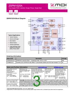
Figure 2.2 Block Diagram...................................................................................................................................13
Figure 2.3 Pin-out QFN24 Package...................................................................................................................15
Figure 3.1 Simplified Block Diagram of the Digital Compensation ....................................................................17
Figure 3.2 Power Sequencing............................................................................................................................18
Figure 3.3 Power Sequencing with Non-zero Off Voltage .................................................................................18
Figure 3.4 Inductor Current Sensing Using the DCR Method............................................................................19
Figure 4.1 PMBus™ Timing Diagram ................................................................................................................22
Figure 5.1 Application Circuit with a 5V Supply Voltage....................................................................................33
© 2013 Zentrum Mikroelektronik Dresden AG — Rev. 1.00
All rights reserved. The material contained herein may not be reproduced, adapted, merged, translated, stored, or used without the
prior written consent of the copyright owner. The information furnished in this publication is subject to changes without notice.
Data Sheet
October 24, 2013
5 of 46

 ETC [ ETC ]