ZSPM1025A
True Digital PWM Controller (Single-Phase, Single-Rail)
4
PMBus™ Functionality
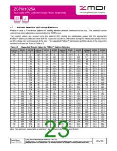
4.1. Introduction
The ZSPM1025A supports the PMBus™ protocol to enable configuration, monitoring, and fault management
during run-time.
The PMBus™ host controller is connected to the ZSPM1025A via the PMBus™ pins (SDA and SCL). A dedicated
SMBALERT pin is provided to notify the host that new status information is present.
The ZSPM1025A supports packet error correction (PEC) according to the PMBus™ specification.
4.2. Timing and Bus Specification
Timing for the PMBus™ signals is given in Figure 4.1. The PMBus™ signal SMBCLK is the shift clock input on
the SCL pin on the ZSPM1025A (slave only) and the SMBDAT signal is the shift data input/output on the SDA pin.
Figure 4.1
PMBus™ Timing Diagram
tHIGH
tLOW
tR
tF
SMBCLK
tBUF
tHD:DAT
tSU:STA
tSU:STO
tHD:STA
SMBDAT
P
S
S
P
tSU:DAT
Table 4.1
PMBus™ Timing Specification
PARAMETER SYMBOL
CONDITIONS
MIN
10
TYP
MAX
UNITS
SMBus operation frequency
Bus free time between start and stop
Hold time after start condition
Repeat start condition setup time
Stop condition setup time
Data hold time
fSMB
400
500
kHz
µs
µs
µs
µs
ns
ns
µs
µs
µs
ms
ns
ns
tBUF
1.3
0.6
0.6
0.6
300
100
tHD:STA
tSU:STA
tSU:STO
tHD:DAT
tSU:DAT
tTIMEOUT
tLOW
Data setup time
Clock low time-out
25
35
Clock low period
1.3
0.6
Clock high period
tHIGH
Cumulative clock low extend time
Clock or data fall time
tLOW:SEXT
tF
25
300
300
Clock or data rise time
tR
© 2013 Zentrum Mikroelektronik Dresden AG — Rev. 1.00
All rights reserved. The material contained herein may not be reproduced, adapted, merged, translated, stored, or used without the
prior written consent of the copyright owner. The information furnished in this publication is subject to changes without notice.
Data Sheet
October 24, 2013
22 of 46

 ETC [ ETC ]