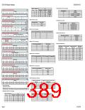
S1D13506 Register Summary
X25B-R-001-02
11 REG[01Eh] Minimum Memory Timing Selection
Pin
MA10/GPIO1
GPIO1
MD14 on
Reset
MD[7:6] on
Reset
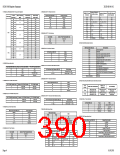
REG[1E2h] LOOK-UP TABLE ADDRESS REGISTER
RW
MA9/GPIO3
GPIO3
MA9
MA11/GPIO2
VMPEPWR
VMPEPWR
VMPEPWR
MA11
Wait State Bits [1:0]
Condition
no restrictions
LUT Address
Bit 4 Bit 3
1
1
1
1
00
01
10
11
00
01
10
11
Bit 7
Bit 6
Bit 5
Bit 2
n/a
Bit 1
n/a
Bit 0
RW
n/a
GPIO1
2 * period (MCLK) - 4ns > period(BCLK)
period(MCLK) - 4ns > period(BCLK)
Reserved
MA9
GPIO1
REG[1E4h] LOOK-UP TABLE DATA REGISTER
MA9
MA10
LUT Data
n/a
n/a
Bit 3
Bit 2
Bit 1
Bit 0
4
REG[010h] MCLK Source Select
12 REG[020h] Memory Type Select
REG[1F0h] POWER SAVE CONFIGURATION REGISTER
RW
MCLK Source Select
MCLK Source
Reserved
Power Save
Mode Enbl
n/a
n/a
n/a
n/a
n/a
n/a
Memory Type Bits [1:0]
Memory Type
0
1
CLKI
00
01
10
11
EDO-DRAM with 2-CAS#
FPM-DRAM with 2-CAS#
EDO-DRAM with 2-WE#
FPM-DRAM with 2-WE#
BUSCLK
REG[1F1h] POWER SAVE STATUS REGISTER
RO
Memory
LCD Power Controller
Save Status Power Save
Status
n/a
n/a
n/a
n/a
n/a
5
REG[014h] LCD PCLK Divide Select
LCD PCLK Divide Select Bits [1:0]
LCD PCLK Source to LPCLK Frequency Ratio
13 REG[021h] DRAM Refresh Select
REG[1F4h] CPU-TO-MEMORY ACCESS WATCHDOG TIMER REGISTER
CPU-to-Memory Access Watchdog Timer
RW
00
01
10
11
1:1
2:1
3:1
4:1
n/a
n/a
DRAM Refresh Select Bits [1:0]
DRAM Refresh Type
CBR Refresh
Bit 5
Bit 4
Bit 3
Bit 2
Bit 1
Bit 0
RW
00
01
1X
32
Self-Refresh
REG[1FCh] DISPLAY MODE REGISTER
No Refresh
Display Mode Select
Bit 1
SwivelView
Enable Bit 0
n/a
n/a
n/a
n/a
6
7
8
9
REG[014h] LCD PCLK Source Select
Bit 2
Bit 0
RW
14 REG[021h] DRAM Refresh Rate
LCD PCLK Source Select Bits [1:0]
LCD PCLK Source
CLKI
REG[1000h] MEDIAPLUG LCMD REGISTER
00
01
10
11
MediaPlug LCMD
DRAM Refresh
Rate Bits [2:0]
MCLK Source Divide
Amount
Refresh Rate for 40MHz
MCLK Source
DRAM Refresh
BUSCLK
CLKI2
Bit 7
Bit 6
Bit 5
Bit 4
Bit 3
Bit 2
Bit 1
Bit 9
Bit 0
Bit 8
Time/256 cycles
0.4 ms
Bit 15
Bit 14
Bit 13
Bit 12
Bit 11
Bit 10
000
001
010
011
100
101
110
111
64
625 kHz
312 kHz
156 kHz
78 kHz
39 kHz
20 kHz
10 kHz
5 kHz
MCLK
128
0.8 ms
REG[1002h] MEDIAPLUG RESERVED LCMD REGISTER
MediaPlug Reserved LCMD
RW
256
1.6 ms
512
3.3 ms
REG[018h] CRT/TV PCLK Divide Select
Bit 23
Bit 31
Bit 22
Bit 30
Bit 21
Bit 29
Bit 20
Bit 28
Bit 19
Bit 27
Bit 18
Bit 26
Bit 17
Bit 25
Bit 16
Bit 24
1024
2048
4096
8192
6.6 ms
13.1 ms
26.2 ms
52.4 ms
CRT/TV PCLK Divide Select Bits [1:0]
CRT/TV PCLK Source to DPCLK Frequency Ratio
00
01
10
11
1:1
2:1
3:1
4:1
REG[1004h] MEDIAPLUG CMD REGISTER
RW
MediaPlug CMD
Bit 7
Bit 6
Bit 5
Bit 4
Bit 12
Bit 3
Bit 2
Bit 1
Bit 9
Bit 0
Bit 8
Bit 15
Bit 14
Bit 13
Bit 11
Bit 10
REG[1006h] MEDIAPLUG RESERVED CMD REGISTER
MediaPlug Reserved CMD
RW
REG[018h] CRT/TV PCLK Source Select
Bit 23
Bit 31
Bit 22
Bit 30
Bit 21
Bit 29
Bit 20
Bit 28
Bit 19
Bit 27
Bit 18
Bit 26
Bit 17
Bit 25
Bit 16
Bit 24
CRT/TV PCLK Source Select Bits [1:0]
CRT/TV PCLK Source
00
01
10
11
CLKI
BUSCLK
CLKI2
REG[1008h] TO REG[1FFEh], even address MEDIAPLUG DATA REGISTERS
RW
MediaPlug Data
MCLK
Bit 7
Bit 6
Bit 5
Bit 4
Bit 3
Bit 2
Bit 1
Bit 9
Bit 0
Bit 8
Bit 15
Bit 14
Bit 13
Bit 12
Bit 11
Bit 10
REG[01Ch] MediaPlug Clock Divide Select
A20-A0 = 100000h-1FFFFEh, even address BITBLT DATA REGISTER 0
RW
BitBlt Data
MediaPlug Clock Divide Select
Bits [1:0]
MediaPlug Clock Source to CRT/TV Pixel Clock
Frequency Ratio
Bit 7
Bit 6
Bit 5
Bit 4
Bit 3
Bit 2
Bit 1
Bit 9
Bit 0
Bit 8
00
01
10
11
1:1
2:1
3:1
4:1
Bit 15
Bit 14
Bit 13
Bit 12
Bit 11
Bit 10
1
2
3
N/A bits should be written 0.
Reserved bits must be written 0.
REG[000h] These bits are used to identify the S1D13506. For the S1D13506 the product code should be 4; the
revision code should be 1. The host interface must be enabled before reading this register (set REG[001] b7=0).
REG[004h] MA[11:9]/GPIO[1:3] Pin Functionality
10 REG[01Ch] MediaPlug Clock Source Select
Pin
MA10/GPIO1
GPIO1
MD14 on
Reset
MD[7:6] on
Reset
MediaPlug Clock Source Select Bits [1:0]
MediaPlug Clock Source
MA9/GPIO3
GPIO3
MA9
MA11/GPIO2
GPIO2
00
01
10
11
CLKI
BUSCLK
CLKI2
0
0
0
0
00
01
10
11
GPIO1
GPIO2
MA9
GPIO1
GPIO2
MCLK
MA9
MA10
MA11
Page 3
01/02/08

 EPSON [ EPSON COMPANY ]