Epson Research and Development
Page 61
Vancouver Design Center
10 2D BitBLT Engine
The term BitBLT is an acronym for Bit Block Transfer. During a BitBLT operation data is
transferred from one memory location (source) to another memory location (destination).
With current graphical user interfaces (GUIs) this term generally refers to the transfer of
bitmap images to or from video memory (display buffer).
The resulting bitmap image may be derived from up to three items or operands:
• the source data.
• an optional pattern.
• the current destination data.
The operands are combined using logical AND, OR, XOR and NOT operations. The
combining process is called a Raster Operation (ROP). The S1D13506 2D Accelerator
supports all possible 16 ROPs between source data and destination data. The destination is
always the display buffer and the source is either data in the display buffer, a pattern in the
display buffer, or data provided by the host CPU.
The 2D BitBLT Engine in the S1D13506 is designed to increase the speed of the most
common GUI operations by off-loading work from the CPU, thus reducing traffic on the
system bus and improving the efficiency of the display buffer interface. The 2D BitBLT
Engine is designed to work at color depths of 8 bpp, 15 bpp, and 16 bpp.
10.1 Registers
The BitBLT control registers on the S1D13506 are located at registers 100h through 119h.
The following is a description of all BitBLT registers.
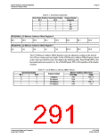
REG[100h] BitBLT Control Register 0
BitBLT FIFO BitBLT FIFO BitBLT FIFO
BitBLT
Destination SourceLinear
Linear Select Select
BitBLT
BitBLT Active
Status
Not Empty
Half Full
Full Status
(RO)
n/a
n/a
Status (RO)
Status (RO)
The BitBLT Active Status bit has two data paths, one for write and one for read.
Write Data Path
When this bit is set to 1, the BitBLT as selected in the BitBLT Operation Register
(REG[103h]) is started.
Read Data Path
When this bit is read, it returns the status of the blit engine. When a read from this bit returns
0, the blit engine is idle and is ready for the next operation. When a read from this bit returns
a 1, the blit engine is busy.
Programming Notes and Examples
Issue Date: 01/02/06
S1D13506
X25B-G-003-03

 EPSON [ EPSON COMPANY ]