Preliminary EN29GL064
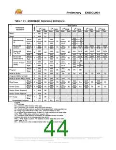
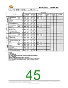
Table 14-2. EN29GL064 Command Definitions
Bus Cycles
Command
1st
Addr Data Addr Data Addr
555 AA 2AA 55 555
P
Cycle
2nd
P
Cycle
3rd
P
Cycle
4th
P
Cycle
5th
P
Cycle
6th
Cycle
P
P
P
P
P
P
P
Sequence
Data Addr Data
Addr Data Addr Data
Word
Byte
3
3
2
1
2
3
3
2
2
1
2
3
3
2
1
40
Command Set
Entry
AAA AA
XXX A0
55
55
AAA 40
Data
Program
XXX
Read
00
XXX 90
555 AA
RD
Command Set Exit
XXX 00
2AA 55
Word
Byte
555
C0
PPB Command
Set Entry
AAA AA
XXX A0
XXX 80
SA RD
XXX 90
55
SA
00
55
00
30
AAA C0
PPB Program
All PPB Erase
PPB Status Read
PPB Command Set Exit
XXX 00
2AA 55
PPB Lock
Command Set
Entry
Word
Byte
555
AA
555
50
AAA AA
XXX A0
XXX RD
555
55
AAA 50
PPB Lock Set
XXX 00
PPB Lock Status Read
PPB Lock Command Set
Exit
2
XXX 90
XXX 00
2AA 55
Word
Byte
3
3
2
2
1
2
555
AA
555
E0
DYB Command
Set Entry
AAA AA
XXX A0
XXX A0
SA RD
XXX 90
555
SA
SA
55
00
01
AAA E0
DYB Set
DYB Clear
DYB Status Read
DYB Command Set Exit
XXX 00
Legend
X = Don’t care
RD(0) = Read data.
SA = Sector Address. Address bits Amax–A16 uniquely select any sector.
PWD = Password
PWDx = Password word0, word1, word2, and word3.
Data = Lock Register Contents: PD(0) = Secured Silicon Sector Protection Bit,
PD(1) = Persistent Protection Mode Lock Bit, PD(2) = Password Protection
Mode Lock Bit.
This Data Sheet may be revised by subsequent versions
or modifications due to changes in technical specifications.
©2004 Eon Silicon Solution, Inc., www.eonssi.com
45
Rev. A, Issue Date: 2009/3/20

 EON [ EON SILICON SOLUTION INC. ]