EN5339QI
Application Information
Low ESR MLCC capacitors with X5R or X7R or
equivalent dielectric should be used for the input
capacitors. Y5V or equivalent dielectrics lose too
much capacitance with frequency, DC bias, and
temperature. Therefore, they are not suitable for
switch-mode DC-DC converter filtering, and must
be avoided.
Setting the Output Voltage
The EN5339 uses a simple and flexible resistor
divider network to program the output voltage. A
feed-forward capacitor (Ca) is used to improve
transient response. Table
3
shows the
recommended component values for the feedback
network as a function of VOUT. It is recommended
to use 1% or better feedback resistors to ensure
output voltage accuracy. The Ra resistor value is
fixed at 348k as shown in Table 3. Based on that
value, the bottom resistor Rb can be calculated
below as:
Table 1: Recommended Input Capacitors
Description
MFG
Taiyo
Yuden
P/N
LMK212BBJ226MG-T
22µF, 10V,
X5R, 0805
GRM21BR61A226ME
51
Murata
Output Filter Capacitor Selection
Ra×0.6V
Rb =
VOUT − 0.6V
The EN5339QI output capacitor selection may be
determined based on two configurations. Table 3
provides the recommended output capacitor
configurations based on operating conditions. For
lower output ripple, choose 3 x 22µF for the output
capacitors. For smaller solution size, use two 47µF
The VOUT is the nominal output voltage. The Rb
and Ra resistors have the same units based on the
above equation.
output
capacitors.
Table
2
shows
the
recommended type and brand of output capacitors
to use. For details regarding other configurations,
contact Enpirion (techsupport@enpirion.com).
Table 2: Recommended Output Capacitors
Description
MFG
Taiyo
Yuden
P/N
JMK212BBJ476MG-T
47µF, 6.3V,
X5R, 0805
Murata
GRM21BR60J476ME15
LMK212BBJ226MG-T
GRM21BR61A226ME51
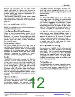
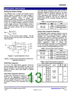
Figure 5. Typical Application Circuit.
Taiyo
Yuden
22µF, 10V,
X5R, 0805
Murata
(NOTE: Enable can be separated from PVIN if the
application requires it)
Table 3. Typical Recommended Components
(Note: Follow Layout Recommendations)
AVIN Filter Capacitor
Ra
(kΩ)
Ca
(pF)
A 1.0 µF, 10V, 0402 MLCC capacitor should be
placed between AVIN and AGND as close to the
pins as possible. This will provide high frequency
bypass to ensure clean chip supply for optimal
performance.
VIN (V) IOUT VOUT
COUT
0.9V
1V
3x 22µF
(0805)
1.2V
10
2.5
to
5.5
1.5V
1.8V
2.5
Input Filter Capacitor Selection
3A
Or
348
A single 22µF, 0805 MLCC capacitor is needed on
PVIN for all applications. Connect the input
capacitor between PVIN and PGND as close to the
pins as possible. Placement of the input capacitor
is critical to ensure low conducted and radiated
EMI.
2x 47µF
(0805)
2.85V
3.3V
8.2
Enpirion 2012 all rights reserved, E&OE
www.enpirion.com, Page 13
06903
September 12, 2012
Rev: B

 ENPIRION [ ENPIRION, INC. ]