Connectivity for
Business-Critical Continuity
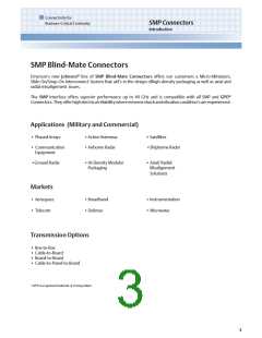
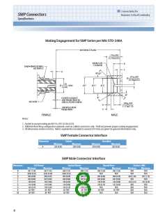
SMP Connectors
Specifications
ENVIRONMENTAL SPECIFICATIONS
(Meets or Exceeds the Applicable Paragraph of MIL-PRF-39012)
Operating Temperature: -65°C to +165°C
Thermal Shock: MIL-STD-202, Method 107, Condition B (except high temp +165°C or max high temp of cable)
Corrosion: MIL-STD-202, Method 101, Condition B
Shock (specified pulse): MIL-STD-202, Method 213, Condition I
Vibration: MIL-STD-202, Method 204, Condition D
Moisture Resistance: MIL-STD-202, Method 106 (except step 7b omitted)
MATERIAL SPECIFICATIONS
Spring Finger (female) and End Launch (male) Bodies: Beryllium Copper per ASTM B196,
Gold* plated per MIL-DTL-45204 (.00005” min)
Hermetic Seal Bodies (male): Kovar Alloy per ASTM F15, Gold* plated per MIL-DTL-45204 (.00005” min)
All other Shroud Bodies (male): Stainless Steel, Type 303, per ASTM A582, Passivated per MIL-DTL-14072 (EL 300)
Connector and Adapter Contacts (male and female): Beryllium Copper per ASTM B196,
Gold* plated per MIL-DTL-45204 (.00005” min)
Hermetic Seal Center Pins: Kovar Alloy per ASTM F15, Gold* plated per MIL-DTL-45204 (.00005” min)
EMI/Anti-Rock Rings: Beryllium Copper per ASTM B196, Gold* plated per MIL-DTL-45204 (.00003” min)
PC Mount Legs: Brass per ASTM B16, Gold* plated per MIL-DTL-45204 (.00003” min)
Connector and Adapter Insulators: PTFE per ASTM D1710
Hermetic Seal Glass: Corning 7070
*All gold plated parts include a .00005” min nickel barrier layer.
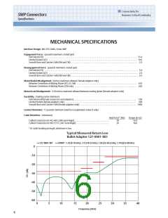
MOUNTING HOLES
Fig 1
Fig 2
Fig 3
This pattern is for reference only.
Pattern will vary depending on board
type and specific electrical and
mechanical requirements.
7

 EMERSON-NETWORKPOWER [ EMERSON NETWORK POWER ]