Connectivity for
Business-Critical Continuity
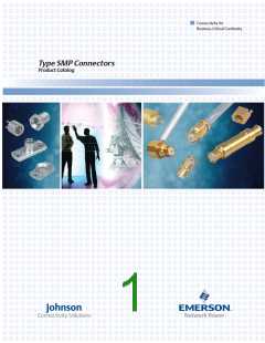
SMP Connectors
Specifications
ELECTRICAL SPECIFICATIONS
Impedance: 50 Ohms
Frequency Range:
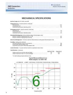
Bullet Adapter (.254 length), Semi-Rigid Straight Cabled Connectors . . . . . . . . . . . . . . . . . . . . . . . . . . . . . . . . . . . . . 0-40 GHz
All other In-Series Adapters, Semi-Rigid Right Angle Cabled Connectors,
Field Replaceable Connectors, End Launch Connectors, Hermetic Feedthroughs . . . . . . . . . . . . . . . . . . . . . . . . . . . . 0-18 GHz
PC Mount Connectors . . . . . . . . . . . . . . . . . . . . . . . . . . . . . . . . . . . . . . . . . . . . . . . . . . . . . . . . . . . . . . . . . . . . . . . . . . . . . . . 0-12 GHz
VSWR: (maximum)
Bullet Adapter (.254 length) . . . . . . . . . . . . . . . . . . . . . . . . . . . . . . . . .1.10
0-18 GHz 18-23 GHz
23-26.5 GHz
1.30
26.5-40 GHz
1.70
1.15
0-18 GHz
18-26.5 GHz
1.35
26.5-40 GH
1.70
Semi-Rigid Straight Cabled Connectors . . . . . . . . . . . . . . . . . . . . . . . . . . . . . . . . . . .20
0-4 GHz
All other In-Series Adapters . . . . . . . . . . . . . . . . . . . . . . . . . . . . . . . . . . . . . . . . . . . 1.10
4-12 GHz
1.15
12-18 GHz
1.20
0-18 GHz
Semi-Rigid Right Angle Cabled Connectors . . . . . . . . . . . . . . . . . . . . . . . . . . . . . . . . . . . . . . . . . . . . . . . . . . . . . . . . . . . 1.20
0-18 GHz
Field Replaceable Connectors (typical, measured back to back with seal pin . . . . . . . . . . . . . . . . . . . . . . . . . . . . . . .1.15
Un-cabled Connectors (dependant on application) . . . . . . . . . . . . . . . . . . . . . . . . . . . . . . . . . . . . . . . . . . . . . . . . Not Applicable
Insertion Loss: (dB maximum, tested at 10 GHz)
In-Series Adapters, Field Replaceable Connectors . . . . . . . . . . . . . . . . . . . . . . . . . . . . . . . . . . . . . . . . . . . . . . . . . 0.10 √ F (GHz)
Semi-Rigid Cabled Connectors . . . . . . . . . . . . . . . . . . . . . . . . . . . . . . . . . . . . . . . . . . . . . . . . . . . . . . . . . . . . . . . . . 0.12 √ F (GHz)
All other Un-cabled Connector . . . . . . . . . . . . . . . . . . . . . . . . . . . . . . . . . . . . . . . . . . . . . . . . . . . . . . . . . . . . . . . . . . Not Applicable
Working Voltage: 335 Vrms maximum at sea level, 65 Vrms maximum at 70,000 feet
Dielectric Withstanding: Voltage: 500 Vrms minimum at sea level
RF High Potential Withstanding Voltage: 325 Vrms minimum at sea level, tested at 4 and 7 MHz
Corona Level: 190 Vrms minimum at 70,000 feet
Contact Resistance: (milliohms maximum initial, not applicable after environmental testing)
Center Contact (Connectors and Adapters) . . . . . . . . . . . . . . . . . . . . . . . . . . . . . . . . . . . . . . . . . . . . . . . . . . . . . . . . . . . . . . . . . 6.0
Outer Contact (Connectors and Adapters) . . . . . . . . . . . . . . . . . . . . . . . . . . . . . . . . . . . . . . . . . . . . . . . . . . . . . . . . . . . . . . . . . . 2.0
Cable Shield to Body (Semi-Rigid Cabled Connectors Only) . . . . . . . . . . . . . . . . . . . . . . . . . . . . . . . . . . . . . . . . . . . . . . . . . . . 0.5
Insulation Resistance: 5000 megohms minimum
RF Leakage: (dB typical, tested at 2.5 GHz)
Cabled and Field Replaceable Connectors . . . . . . . . . . . . . . . . . . . . . . . . . . . . . . . . . . . . . . . . . . . . . . . . . . . . . . . . . . . . . . . . . . . -80
In-Series Adapters . . . . . . . . . . . . . . . . . . . . . . . . . . . . . . . . . . . . . . . . . . . . . . . . . . . . . . . . . . . . . . . . . . . . . . . . . . . . . . . . . . . . . . . -65
All other Un-cabled Connectors . . . . . . . . . . . . . . . . . . . . . . . . . . . . . . . . . . . . . . . . . . . . . . . . . . . . . . . . . . . . . . . . . . Not Applicable
5

 EMERSON-NETWORKPOWER [ EMERSON NETWORK POWER ]