Connectivity for
Business-Critical Continuity
SMP Connectors
Assembly Instructions
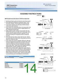
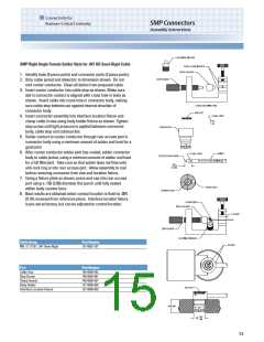
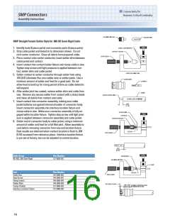
SMP Straight Female Solder Style for .086 OD Semi-Rigid Cable
1. Identify tools (6 piece parts) and connector parts (2 piece parts).
2. Strip cable jacket and dielectric to dimension shown. Do not
nick center conductor. Clean all debris from prepared cable.
3. Place contact onto center conductor, insert solder shim between
cable jacket and contact.
4. Insert contact into contact holder fixture and clamp cable in vise.
Tighten stop screw until light pressure is applied between con-
tact, solder shim and cable jacket.
5. Solder contact to center conductor through solder hole using
.016 (0.41) diameter flux core solder wire or solder paste. Use a
minimum amount of solder and heat for a good joint. Do not
allow heat to build up for a long period of time as cable dielectric
will expand.
6. After solder joint has cooled, remove solder shim and cable from
vise. Remove any excess solder from contact with a sharp blade
and clean all debris from contact and cable.
7. Insert contact into connector assembly, making sure cable
jacket bottoms out against internal shoulder of connector body.
Insert connector assembly into interface location fixture and
clamp cable in vise. Make sure connector assembly is fully en-
gaged within location fixture. Tighten stop screw until light pres-
sure is applied between connector assembly and cable jacket.
8. Solder end of connector body to cable jacket, using a minimum
amount of solder and heat for a full fillet joint. Allow assembly to
cool before removing connector from vise and location fixture.
Best results are obtained when contact location is flush to .004
(0.10) recessed from reference plane. Interface location fixture
is pre-set at factory, but can be adjusted to control location.
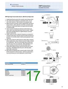
Cable Group
Part Number
RG-405, .086 Semi-Rigid
127-0693-001
Tool
Cable Vise
Stop Screw
Clamp Inserts
Solder Shim
Part Number
140-0000-962
140-0000-981
140-0000-964
140-0000-984
127-0000-902
127-0000-903
Contact Holder
Interface Location Fixture
16

 EMERSON-NETWORKPOWER [ EMERSON NETWORK POWER ]