EM78P809N
8-Bit Microcontroller
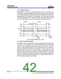
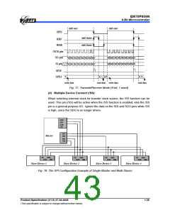
(b) 8-bit Receive Mode:
Setting SPIM0 ~ SPIM1 to receive mode and setting SPIS to “1” to start receiving.
The data are input sequentially from the SI pin in synchronous with the serial
clock. When the final bit of transfer data has been received, the SPI interrupt is
generated and SPIS is cleared to “0” by hardware. In order to receive the next
data, the SPIS must be set to “1” again by software. If the current data is not read
out from the data buffer, receiving is not started when using internal clock.
shiftstart
shiftstart
shiftfinish
RBF
W BE
/SCK pin
SIpin
a0 a1 a2 a3 a4 a5 a6 a7
b0 b1 b2 b3 b4 b5 b6 b7
SPIF
SPID
a
b
readdata
readdata
Fig. 16. Receive Mode (8-bit, 1 word)
(c) 8-bit Transmit/Receive Mode:
Set SPIM0 ~ SPIM1 to transmit/receive mode and write data to data buffer SPID.
Set SPIS to “1” to start transferring. The data are output to the SO pin and input
from the SI pin sequentially in synchronous with the serial clock. When the
number of data words specified has been transferred, the SPI interrupt is
generated and SPIS is cleared to “0” by hardware. In order to receive the next
data, the SPIS must be set to “1” again by software. Writing data in transmit
mode and reading data in receive mode use the same data buffer. If the current
data is not read out from the data buffer and then write the data to data buffer, the
transfer is not started when using internal clock. Always write the data to be
transmitted after reading the received data.
38 •
Product Specification (V1.0) 07.26.2005
(This specification is subject to change without further notice)

 ELAN [ ELAN MICROELECTRONICS CORP ]