EM78P809N
8-Bit Microcontroller
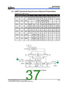
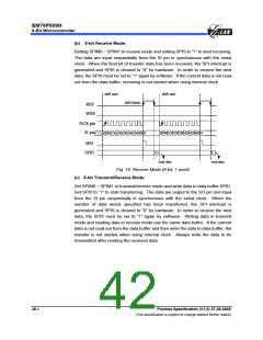
In Universal Asynchronous Receiver Transmitter (UART), each transmitted or received
character is individually synchronized by framing it with a start bit and stop bit.
Full duplex data transfer is possible since the UART has independent transmit and
receive sections. Double buffering for both sections allows the UART to be
programmed for continuous data transfer.
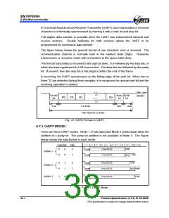
The figure below shows the general format of one character sent or received. The
communication channel is normally held in the marked state (high). Character
transmission or reception starts with a transition to the space state (low).
The first bit transmitted or received is the start bit (low). It is followed by the data bits, in
which the least significant bit (LSB) comes first. The data bits are followed by the parity
bit. If present, then the stop bit or bits (high) confirm the end of the frame.
In receiving, the UART synchronizes on the falling edge of the start bit. When two or
three “0” are detected during three samples, it is recognized as normal start bit and the
receiving operation is started.
Idle state
(mark)
START
bit
Parity STOP
D0
D1
D2
Dn
bit
bit
1 bit
7 or 8 bits
One character or frame
1 bit
1 bits
Fig. 12. DATA Format in UART
4.7.1 UART MODE:
There are three UART modes. Mode 1 (7 bits data) and Mode 2 (8 bits data) allow the
addition of a parity bit. The parity bit addition is not available in Mode 3. The Figure
below shows the data format in each mode.
1
2
3
4
5
6
7
8
9
10 11
UMODE
PRE
0
7 bits DATA
7 bits DATA
STOP
0
0
START
Mode 1
0
0
1
Parity STOP
STOP
START
8 bits DATA
8 bits DATA
0
0
1
1
0
1
START
START
Mode 2
Mode 3
Parity STOP
9 bits DATA
STOP
1
0
X
START
Fig. 13. UART Mode
34 •
Product Specification (V1.0) 07.26.2005
(This specification is subject to change without further notice)

 ELAN [ ELAN MICROELECTRONICS CORP ]