EM78P5840N/41N/42N
8-Bit Microcontrollers
R9 and RA, Page 3 (DT2: PWM2 Duty Cycle)
RA1
RA0
R97
R96
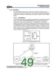
R95
R94
R93
R92
R91
R90
PWM2[9] PWM2[8] PWM2[7] PWM2[6] PWM2[5] PWM2[4] PWM2[3] PWM2[2] PWM2[1] PWM2[0]
A specified value keeps the PWM2 output to remain high until the value matches with
TMR2.
R8, Page 3 (PRD1: PWM1 Period)
Bit 7
Bit 6
Bit 5
Bit 4
Bit 3
Bit 2
Bit 1
Bit 0
PRD1[7] PRD1[6] PRD1[5] PRD1[4] PRD1[3] PRD1[2] PRD1[1] PRD1[0]
This register contains the PWM1 time-base period. The PWM1 frequency is the
inverse of the time-base period.
RB, Page 3 (PRD2: PWM2 Period)
Bit 7
Bit 6
Bit 5
Bit 4
Bit 3
Bit 2
Bit 1
Bit 0
PRD2[7] PRD2[6] PRD2[5] PRD2[4] PRD2[3] PRD2[2] PRD2[1] PRD2[0]
This register contains the PWM2 time-base period. The PWM2 frequency is the
inverse of the time-base period.
7.10.3 Increment Timer Counter (TMRX: TMR1H/TMR1L or
TMR2H/TMR2L)
TMRX are 10-bit clock counters with programmable prescalers. They are designed for
the PWM module as baud rate clock generators. TMRX can be read, written, and
cleared at any reset conditions. If enabled, the rates can be reduced to conserve
power by setting the T1EN bit to “0”.
7.10.4 PWM Period (PRDX: PRD1 or PRD2)
The PWM period is defined by writing to the PRDX register. When TMRX is equal to
PRDX, the following operations are performed on the next increment cycle:
• TMRX is cleared
• The PWMX pin is set to “1”
• The PWM duty cycle is latched from DT1/DT2 to DTL1/DTL2
NOTE
The PWM output will not be set if the duty cycle is 0.
• The PWMXIF pin is set to 1
40 •
Product Specification (V1.0) 04.25.2006
(This specification is subject to change without further notice)

 ELAN [ ELAN MICROELECTRONICS CORP ]