EM78P417N/418N/419N
8-Bit Microprocessor with OTP ROM
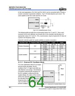
In the most applications, Pin OSCI and Pin OSCO can be connected with a crystal or
ceramic resonator to generate oscillation. Fig. 6-16 below depicts such circuit. The
same applies to the HXT mode and the LXT mode.
C1
OSCI
EM78P417/ 8/ 9N
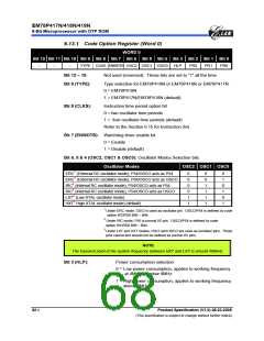
XTAL
OSCO
C2
RS
Fig. 6-16 Crystal/Resonator Circuit
The following table provides the recommended values for C1 and C2. Since each
resonator has its own attribute, you should refer to the resonator specifications for
appropriate values of C1 and C2. RS, a serial resistor, may be required for AT strip cut
crystal or low frequency mode.
Capacitor selection guide for crystal oscillator or ceramic resonators:
Oscillator Type
Frequency Mode
Frequency
C1(pF)
C2(pF)
455 kHz
2.0 MHz
4.0 MHz
32.768kHz
100KHz
200KHz
455KHz
1.0MHz
2.0MHz
4.0MHz
100~150
20~40
10~30
25
100~150
20~40
10~30
15
Ceramic Resonators
HXT
LXT
HXT
25
25
25
25
Crystal Oscillator
20~40
15~30
15
20~150
15~30
15
15
15
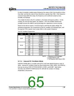
6.11.3 External RC Oscillator Mode
For some applications that do not require
precise timing calculation, the RC
Vcc
oscillator (Fig. 6-17 right) could offer you
with effective cost savings. Nevertheless,
it should be noted that the frequency of
the RC oscillator is influenced by the
supply voltage, the values of the resistor
Rext
OSCI
Cext
(Rext), the capacitor (Cext), and even by
the operation temperature. Moreover, the
frequency also changes slightly from one
chip to another due to the manufacturing
process variation.
EM78P417/ 8/ 9N
Fig. 6-17 External RC Oscillator Mode Circuit
58 •
Product Specification (V1.0) 06.23.2005
(This specification is subject to change without further notice)

 ELAN [ ELAN MICROELECTRONICS CORP ]