DA14580
FINAL
Bluetooth Low Energy 4.2 SoC
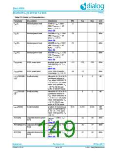
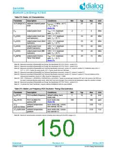
Table 272: Radio: AC Characteristics
Parameter
Description
Conditions
3 MHz; -40C
Min
Typ
Max
Unit
ACP(3M)(EOC) adjacent channel power
level
f
-57
-47
dBm
OFFSET
T +85C
A
(Note 26)
P
output power level
V
= 3 V; maximum
-2
-1
0
dBm
O
DD
gain; T = 25 °C
A
P (HD2)
output power level (sec- VDD = 3 V; maximum
ond harmonic) gain; T = 25 C
-54
-56
-70
-70
-20
-40
-40
-40
-40
-15
dBm
dBm
dBm
dBm
dBm
O
A
P (HD3)
output power level (third VDD = 3 V; maximum
O
harmonic)
gain; T = 25 C
A
P (HD4)
output power level
(fourth harmonic)
VDD = 3 V; maximum
O
gain; T = 25 C
A
P (HD5)
output power level (fifth
harmonic)
VDD = 3 V; maximum
O
gain; T = 25 C
A
P (NFM)
output power level in
'Near Field Mode'
V
= 3 V; maximum
-25
O
DD
gain; T = 25 °C
A
(Note 27)
Note 20: Measured according to Bluetooth® Low Energy Test Specification RF-PHY.TS/4.0.1, section 6.4.1.
Note 21: Measured according to Bluetooth® Low Energy Test Specification RF-PHY.TS/4.0.1, section 6.4.2.
Note 22: Measured according to Bluetooth® Core Technical Specification document, version 4.2, volume 6, section 4.4. Published value is for n =
IXIT = 4 . IXIT = 5 gives the same results, IXIT = 3 gives results that are 5 dB lower.
Note 23: Measured according to Bluetooth® Core Technical Specification document, version 4.2, volume 6, section 4.2.
Note 24: Measured according to Bluetooth® Core Technical Specification document, version 4.2, volume 6, section 4.3. Due to limitations of the
measurement equipment, levels of -5 dBm should be interpreted as > -5 dBm.
Note 25: PRF = PRSSI(min) + LRES(RSSI) x RXRSSI[7:0] ± LACC(RSSI). Thanks to constant gain biasing of RF part in the receiver, the RSSI can
be used to estimate absolute power levels, rather than mere level changes. Even across the full temperature range the variation is limited.
Note 26: Measured according to Bluetooth® Low Energy Test Specification RF-PHY.TS/4.0.1, section 6.2.3.
Note 27: To activate the "Near Field Mode", program address 0x50002418 with the value 0x0030.
Table 273: Stable Low Frequency RCX Oscillator: Timing Characteristics
Parameter
(RCX)
Description
Conditions
Min
Typ
Max
Unit
f
RCX oscillator frequency default setting, buck
mode only
5
10
40
kHz
RC
f (RCX)
RCX oscillator fre-
quency drift
buck mode only
(Note 28)
-500
500
ppm
°C/s
RC
T /
ambient temperature
gradient
buck mode only; connec-
tion interval 100 ms
0.66
A
t(RCX)100ms
T /t(RCX)4s ambient temperature
buck mode only; connec-
tion interval 4 s
0.33
°C/s
A
gradient
Note 28: Maximum recommended connection interval (including slave latency) for the RCX usage is 2 s.
Datasheet
Revision 3.4
09-Nov-2016
CFR0011-120-01
150 of 155
© 2014 Dialog Semiconductor

 DIALOG [ Dialog Semiconductor ]