DA14580
FINAL
Bluetooth Low Energy 4.2 SoC
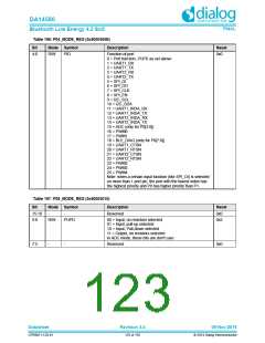
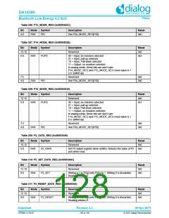
Table 199: P07_MODE_REG (0x50003014)
Bit
Mode Symbol
R/W PID
Description
Reset
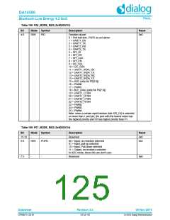
4:0
Function of port
0x0
0 = Port function, PUPD as set above
1 = UART1_RX
2 = UART1_TX
3 = UART2_RX
4 = UART2_TX
5 = SPI_DI
6 = SPI_DO
7 = SPI_CLK
8 = SPI_EN
9 = I2C_SCL
10 = I2C_SDA
11 = UART1_IRDA_RX
12 = UART1_IRDA_TX
13 = UART2_IRDA_RX
14 = UART2_IRDA_TX
15 = ADC (only for P0[3:0])
16 = PWM0
17 = PWM1
18 = BLE_DIAG (only for P0[7:0])
19 = UART1_CTSN
20 = UART1_RTSN
21 = UART2_CTSN
22 = UART2_RTSN
23 = PWM2
24 = PWM3
25 = PWM4
Note: when a certain input function (like SPI_DI) is selected
on more than 1 port pin, the port with the lowest index has
the highest priority and P0 has higher priority than P1.
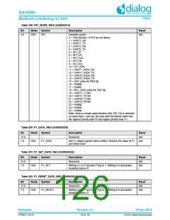
Table 200: P1_DATA_REG (0x50003020)
Bit
Mode Symbol
Description
Reset
0x0
15:8
7:0
-
-
Reserved
R/W
P1_DATA
Set P1 output register when written; Returns the value of P1
port when read
0x0
Table 201: P1_SET_DATA_REG (0x50003022)
Bit
Mode Symbol
Description
Reset
0x0
15:8
7:0
-
-
Reserved
R/W
P1_SET
Writing a 1 to P1[y] sets P1[y] to 1. Writing 0 is discarded;
Reading returns 0
0x0
Table 202: P1_RESET_DATA_REG (0x50003024)
Bit
Mode Symbol
Description
Reset
0x0
15:8
7:0
-
-
Reserved
R/W
P1_RESET
Writing a 1 to P1[y] sets P1[y] to 0. Writing 0 is discarded;
Reading returns 0
0x0
Datasheet
Revision 3.4
09-Nov-2016
CFR0011-120-01
126 of 155
© 2014 Dialog Semiconductor

 DIALOG [ Dialog Semiconductor ]